




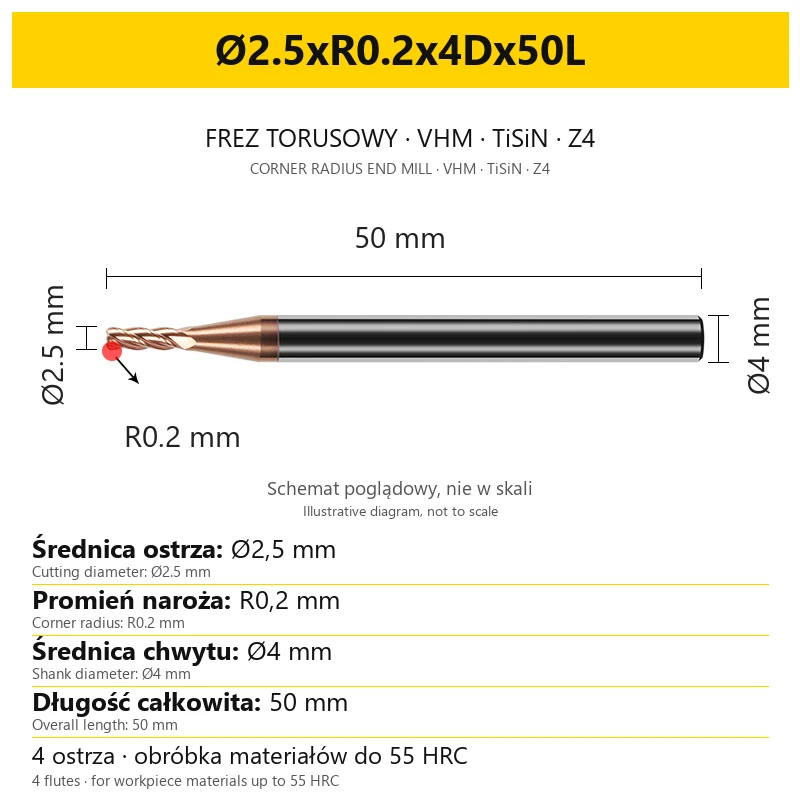


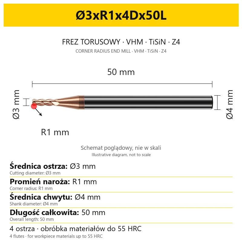


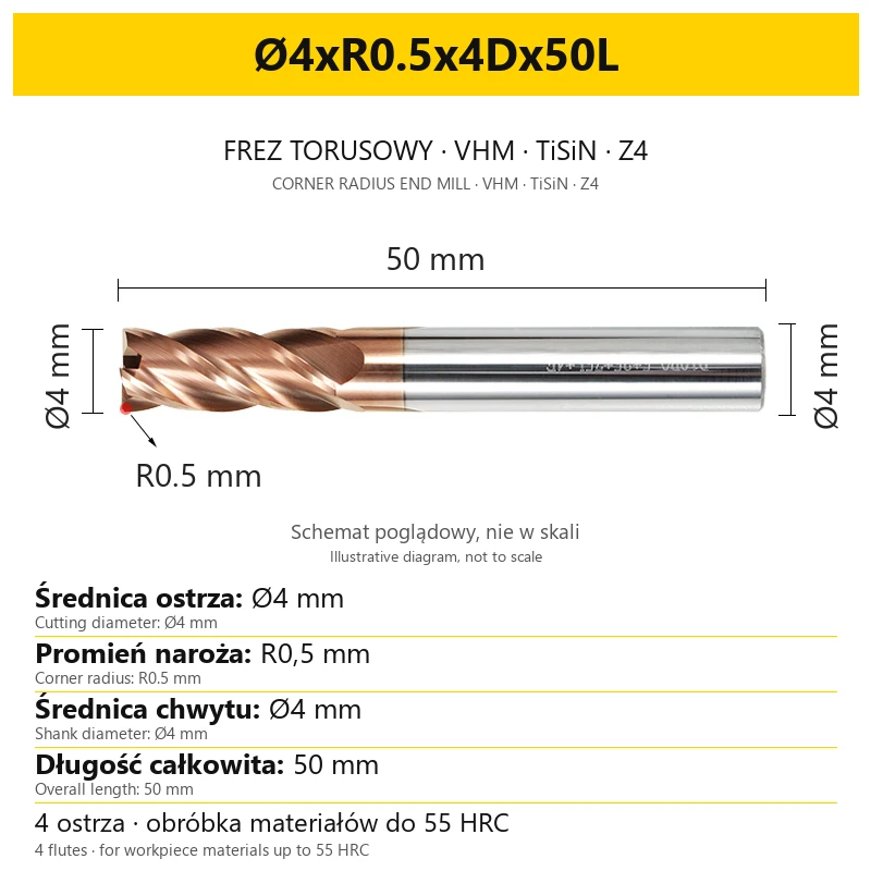
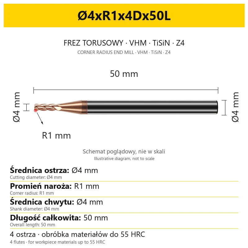


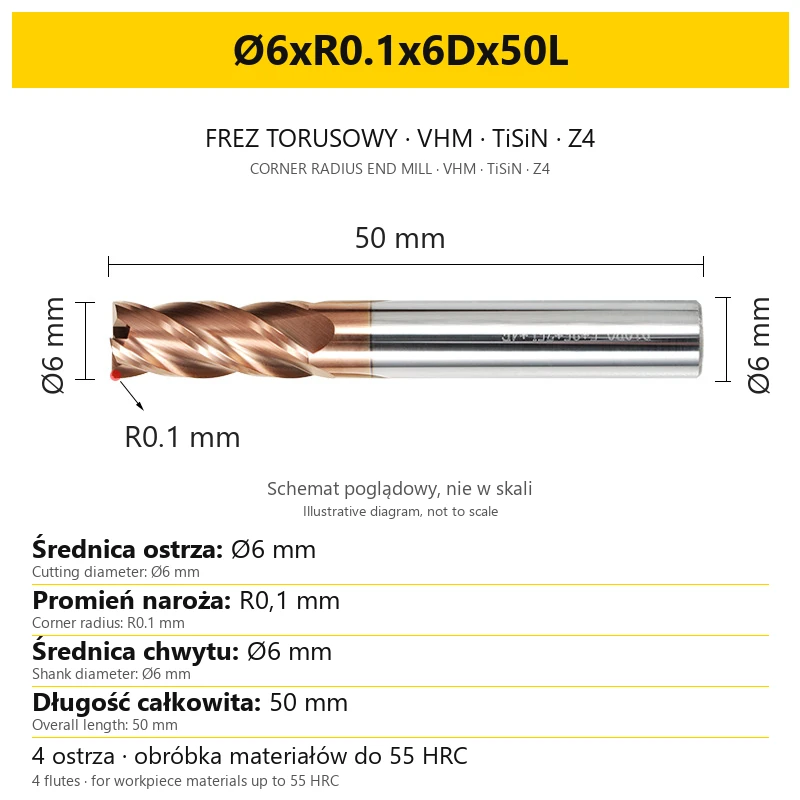


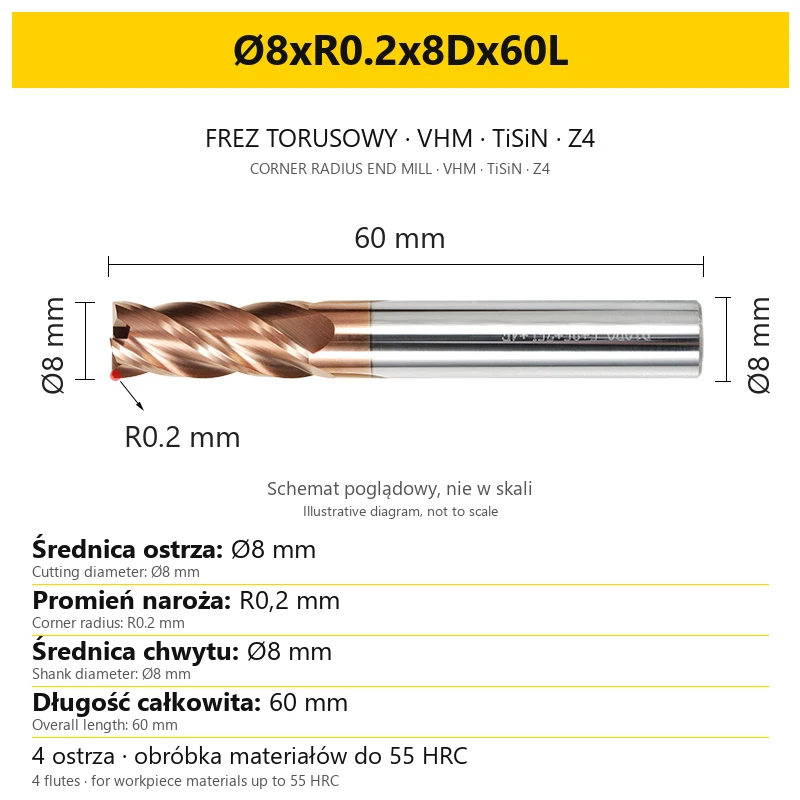


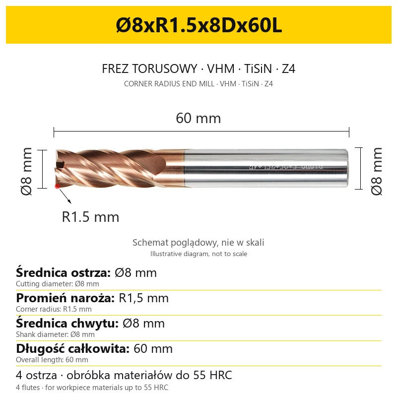


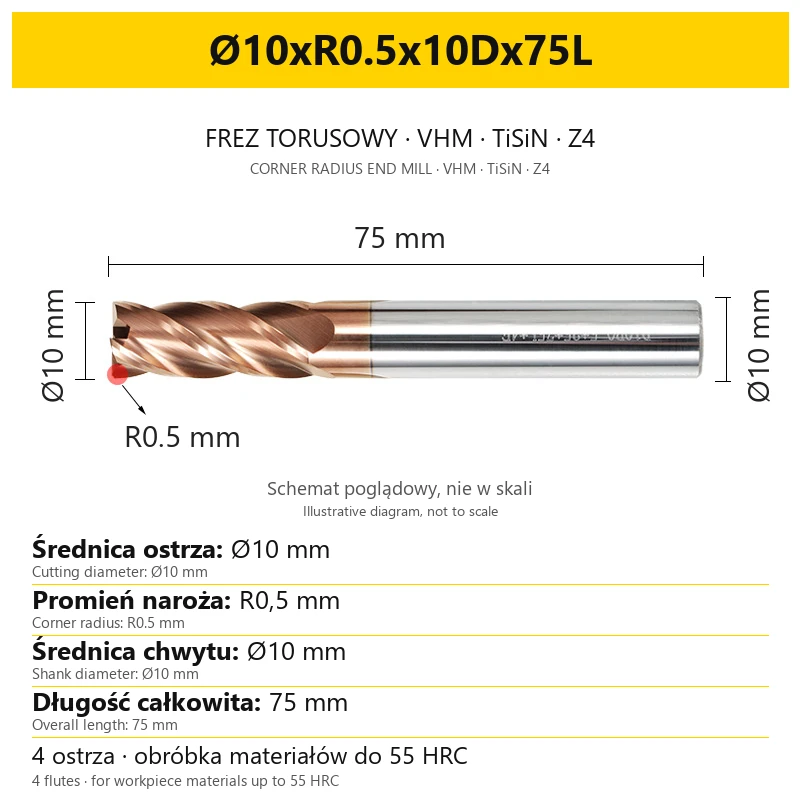














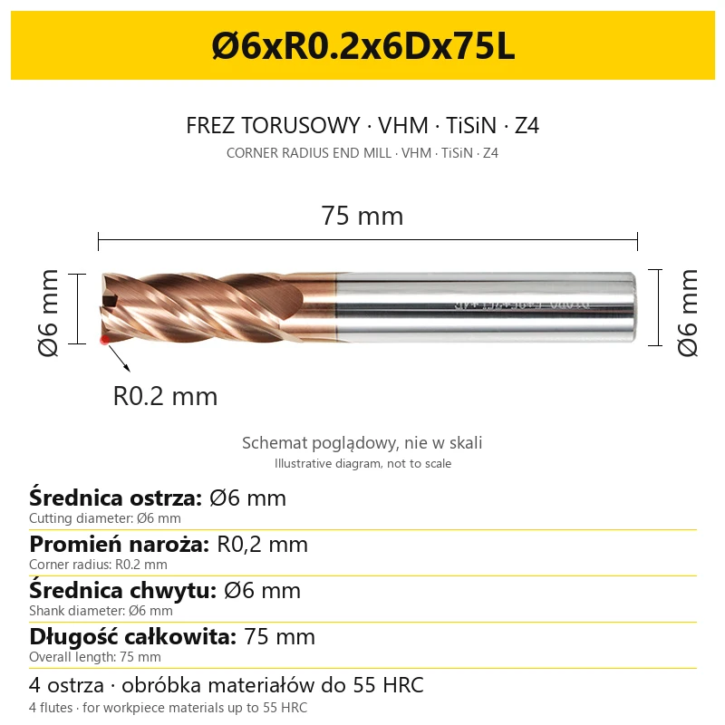


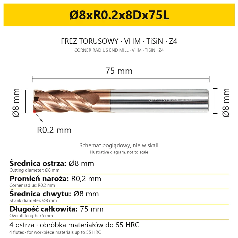
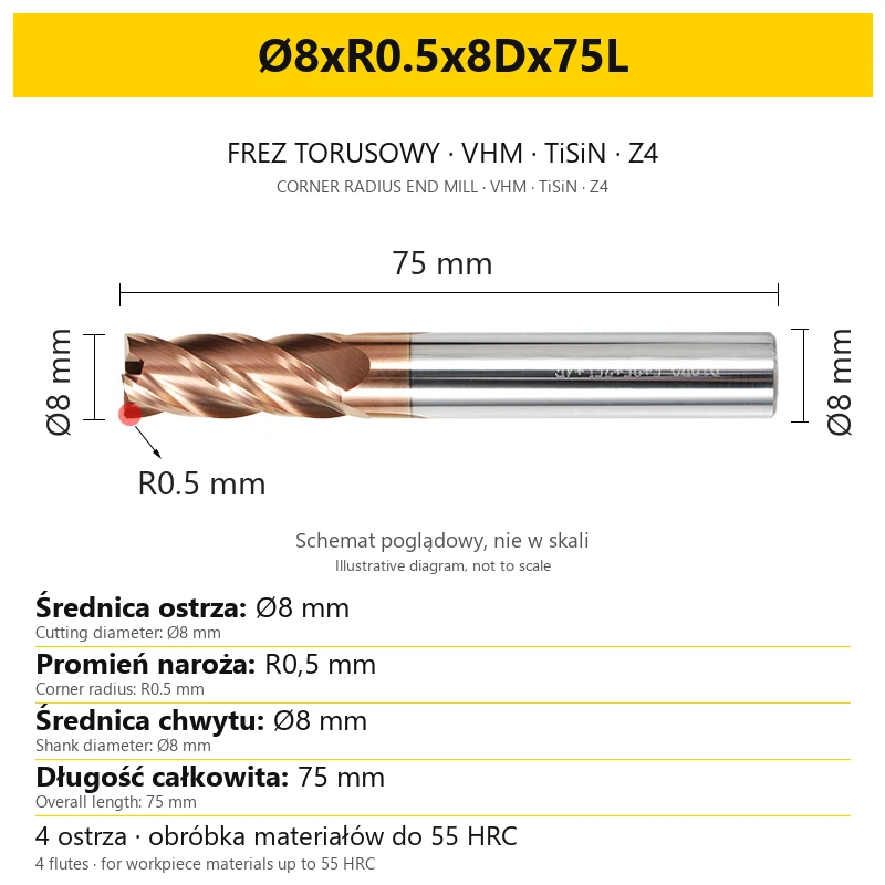

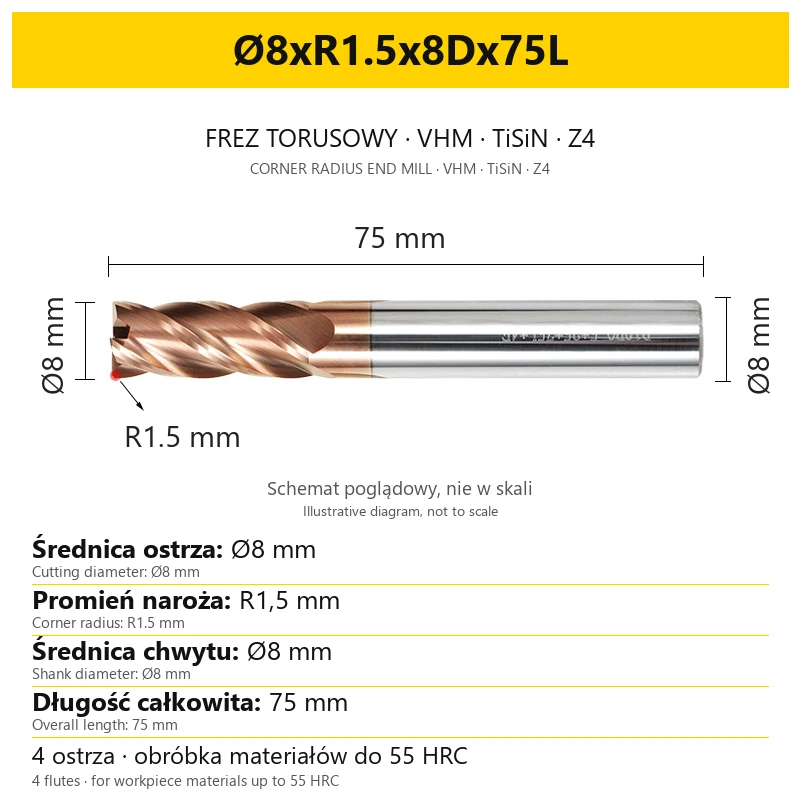





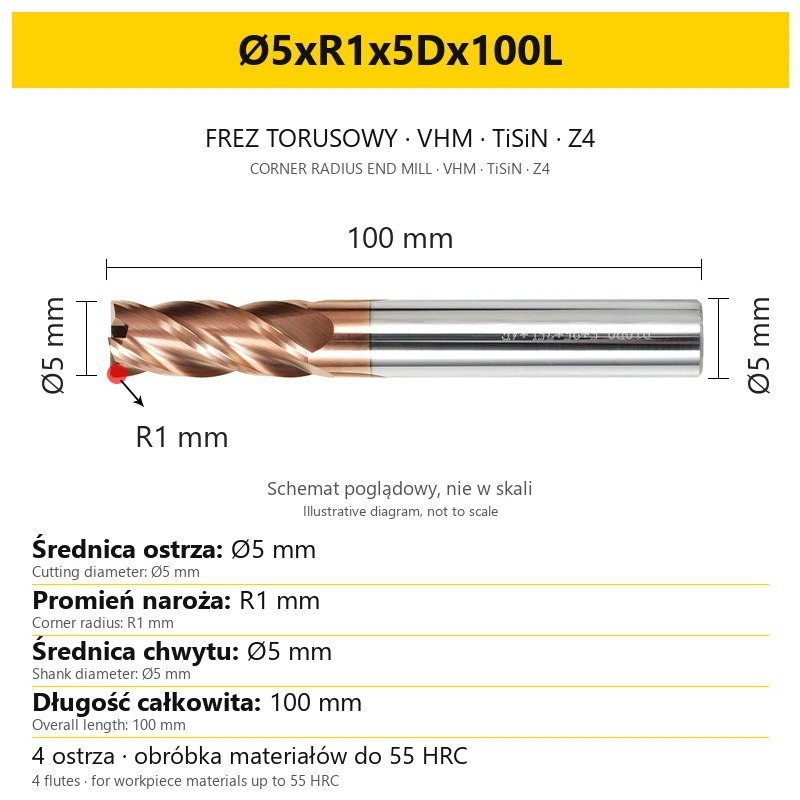


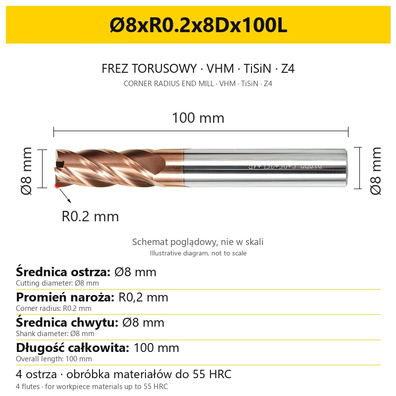

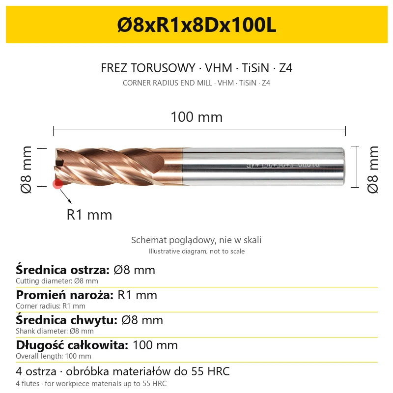


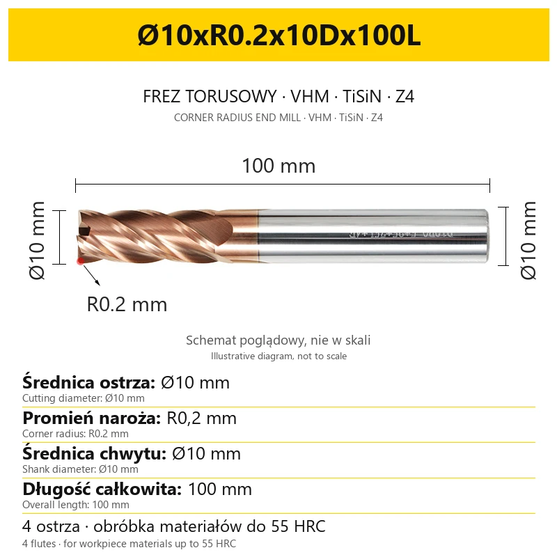

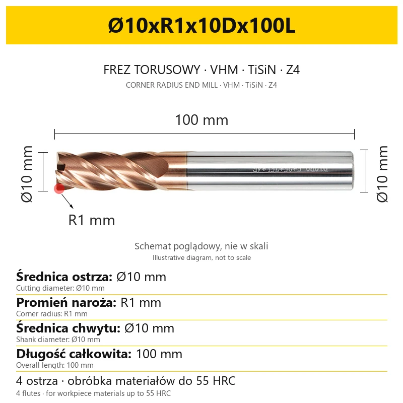
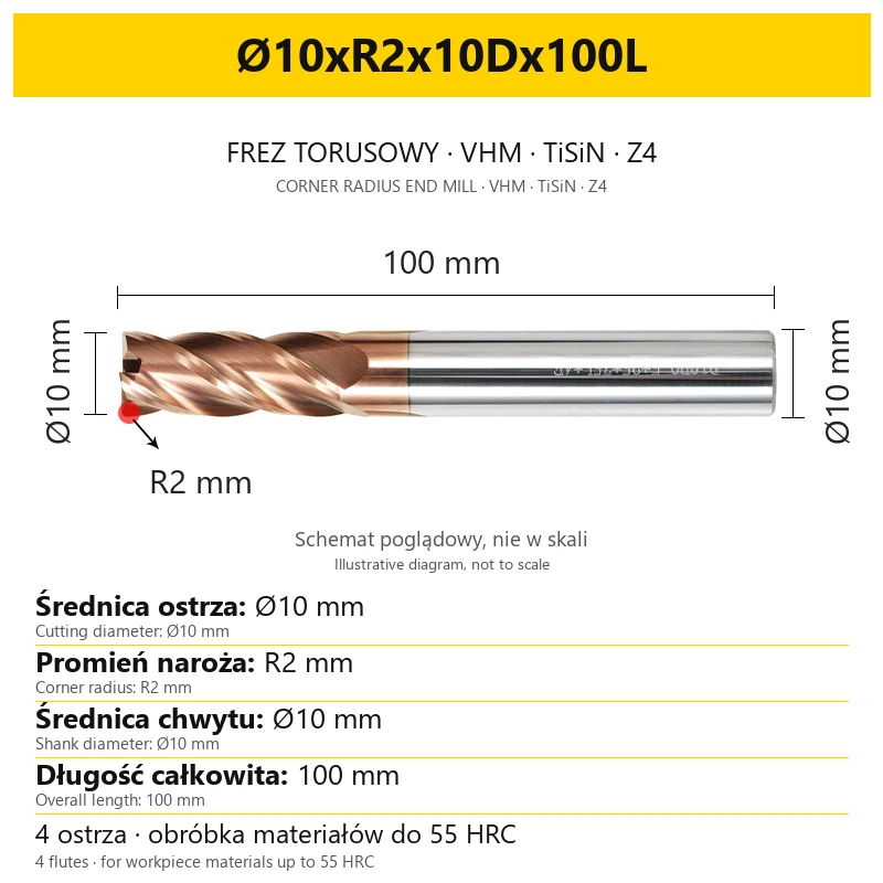
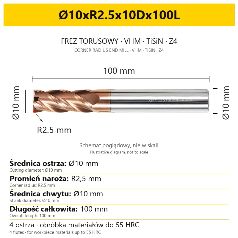
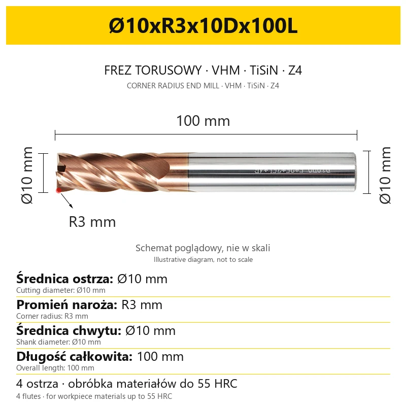










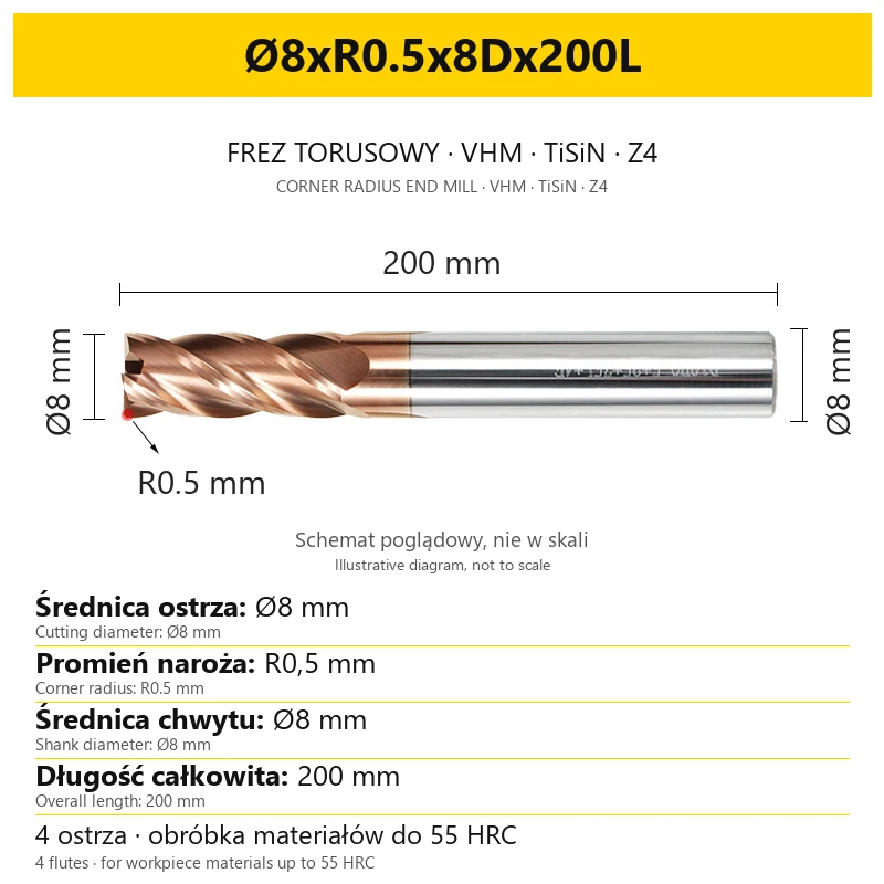


4-Flute TiSiN Coated Carbide Corner Radius End Mill, up to 55HRC
Shipping costs are not included in the price.
Shipping costs are not included in the price.
Ask about the product

The administrator of personal data is Kortools. We process it to respond to your inquiry. More information regarding the processing of personal data can be found in privacy policy.
Select a product variant:
Individual variants may differ in price
Product code: 1670-1921A
Product description
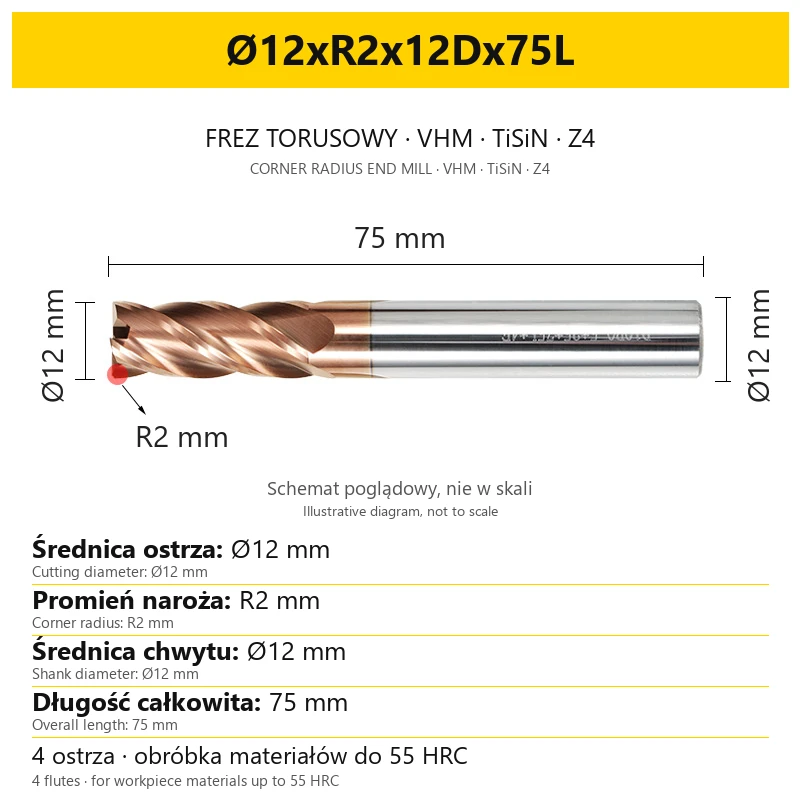
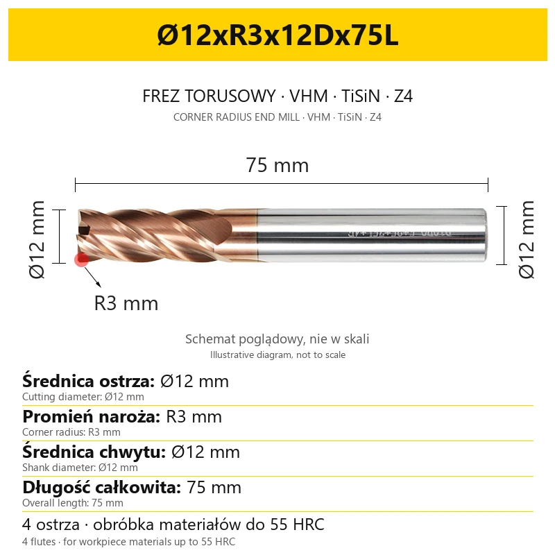
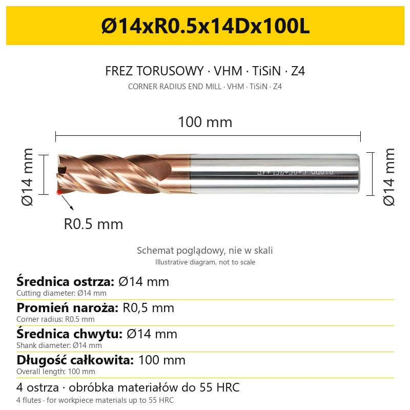
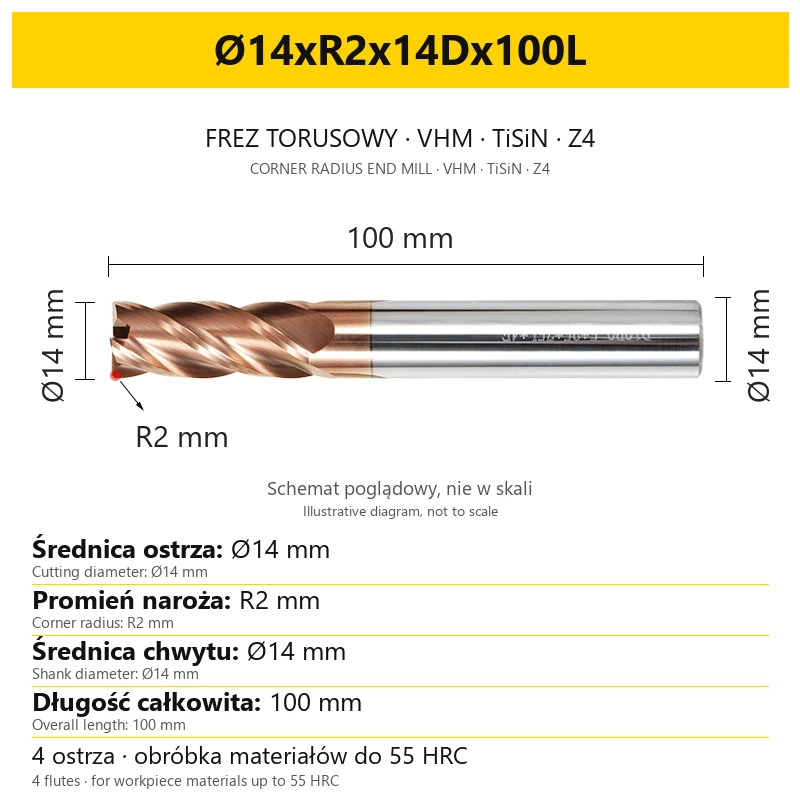
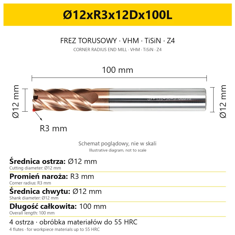
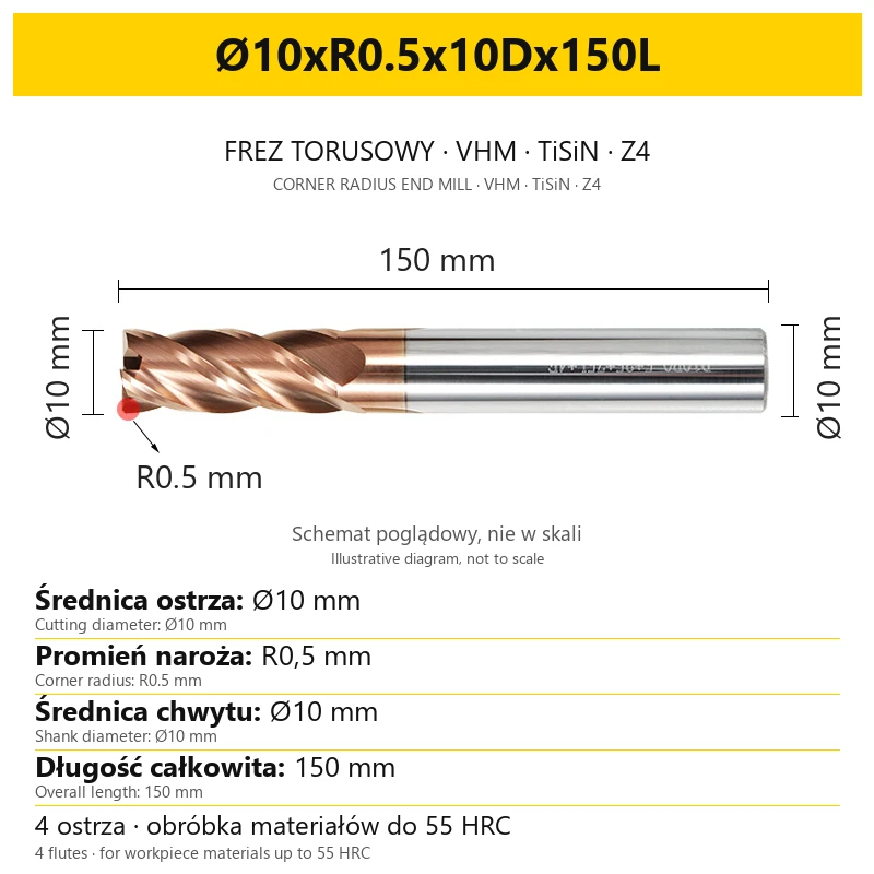
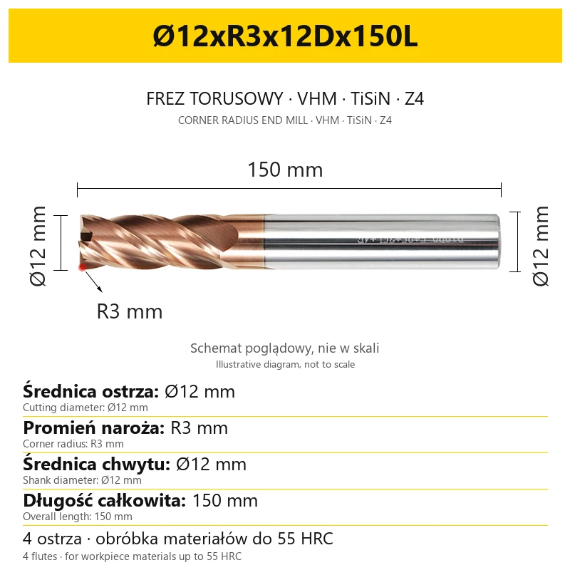
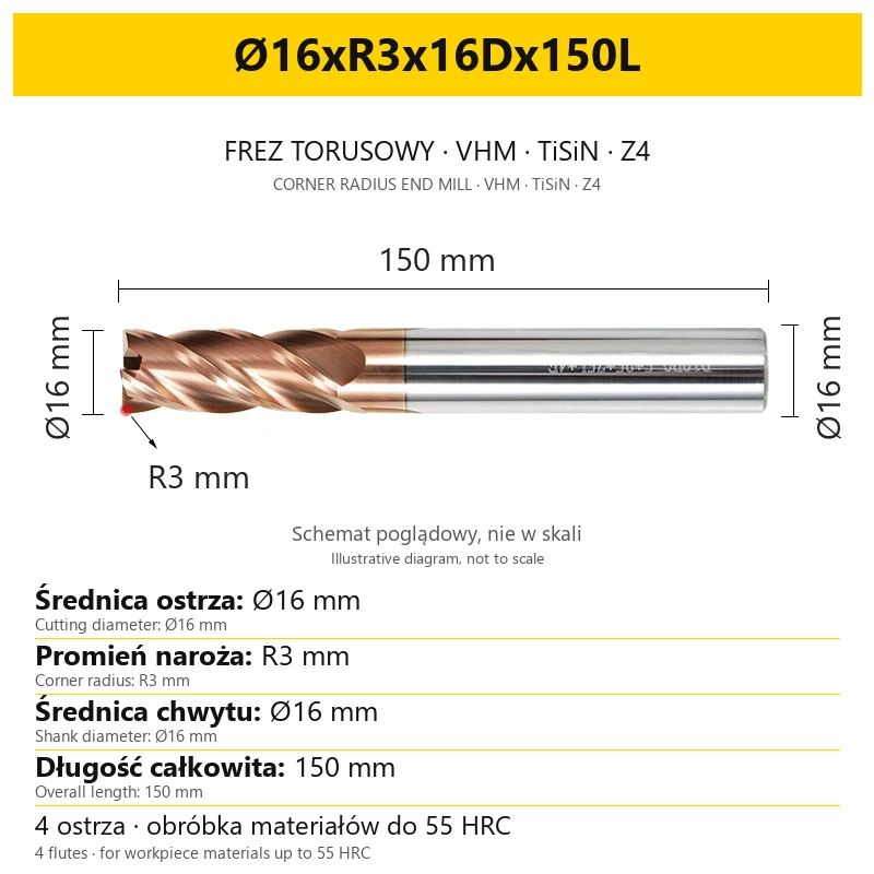
VHM TiSiN Z4 corner radius end mill
Four flutes · corner radius R · for workpiece materials up to 55 HRC
A corner radius end mill, also called a radius end mill, is a solid carbide end mill with a rounded cutting-edge corner. Four flutes and a TiSiN coating make it suitable for milling contours, side surfaces and 3D shape machining. Select the corner radius together with the cutter diameter and overall length.
The series includes diameters Ø1–20 mm and overall lengths 50–200 mm. The complete variant designation defines the dimensions of the selected tool: cutting diameter, radius R, shank diameter and overall length L. Check the individual size combinations in the variant selector.
1. Applications and workpiece materials
The TiSiN Z4 corner radius end mill is intended primarily for machining steel and stainless steel; its application range also includes cast iron. The workpiece material may have a hardness up to 55 HRC. When selecting the tool, consider the specific grade, material condition and operation.
| Material | What to consider |
|---|---|
| Steel | Match the diameter, corner radius and tool reach to the part contour. Material hardness should be within the range up to 55 HRC. |
| Stainless steel — INOX | Match machining conditions to the steel grade, tool path and actual projection length. |
| Cast iron | Consider the cast-iron grade, part geometry and chip evacuation from the machining zone. |
For aluminium, copper, brass, heat-resistant alloys, plastics or non-metallic materials, selection requires checking the specific application. Provide the material and planned operation to determine whether this geometry and coating are suitable.
2. Design and technical parameters
The tool has a solid body made of VHM cemented carbide, four helical flutes and a TiSiN coating. The designation Z4 indicates the number of flutes, while R defines the corner-rounding radius. Select the cylindrical shank for the holder by its own diameter.
| Parameter | Value |
|---|---|
| Tool type | Corner radius end mill |
| Design | Solid carbide |
| Tool material | VHM — cemented carbide |
| Coating | TiSiN |
| Number of flutes | 4 — Z4 |
| Helix angle | 35° |
| Corner geometry | Corner rounding with radius R, depending on the variant |
| Cutting diameter | Ø1–20 mm, depending on the variant |
| Corner radius R | 0.1–3 mm, depending on the variant |
| Shank diameter | Ø3–20 mm, depending on the variant |
| Overall length L | 50, 60, 75, 100, 150 or 200 mm, depending on the variant |
| Workpiece material hardness | Up to 55 HRC |
| Sales unit | 1 piece |
The ranges in the table apply to the entire series. Not every diameter is available with every radius and length. The complete designation of a specific size is shown with the selected variant.
3. Operations for a corner radius end mill
The rounded corner must be accounted for in the part geometry and in the tool definition in the CAM program. Select radius R for the required surface shape and planned toolpath.
| Operation | Selection for the task |
|---|---|
| 3D shape machining and scallop milling | Match the diameter and corner radius to the machined surface. Enter the correct values in the cutter definition in the CAM program. |
| Contour and wall milling | Check the required tool reach and the working position of the rounded corner relative to the part. |
| Pocket and slot machining | Consider the cutter diameter and radius at the transition between the floor and wall. Select a toolpath for the required slot shape. |
| Surface milling | Match the toolpath direction, flute engagement and cutting parameters to the material and surface requirements. |
A corner radius end mill and a ball-nose end mill have different end geometries. Similarity of use in 3D machining does not mean that they can be substituted in a program without updating the tool geometry and checking the toolpath.
4. How to read the variant designation
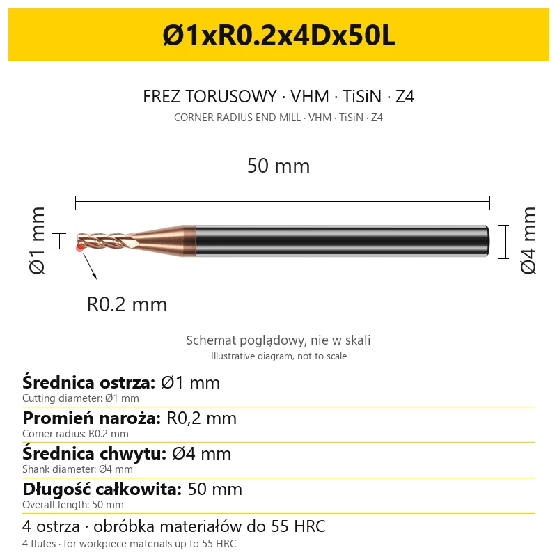
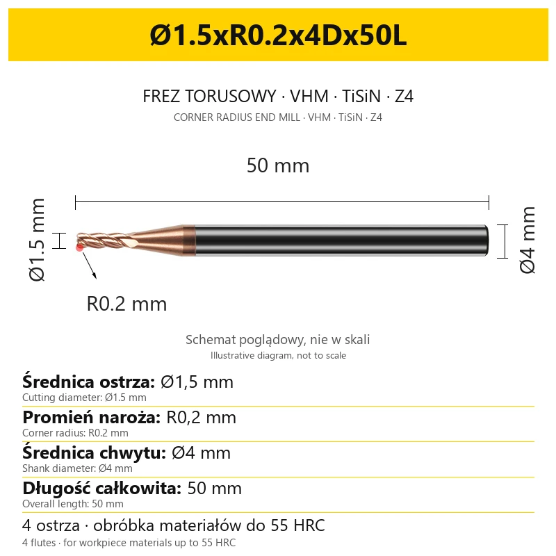
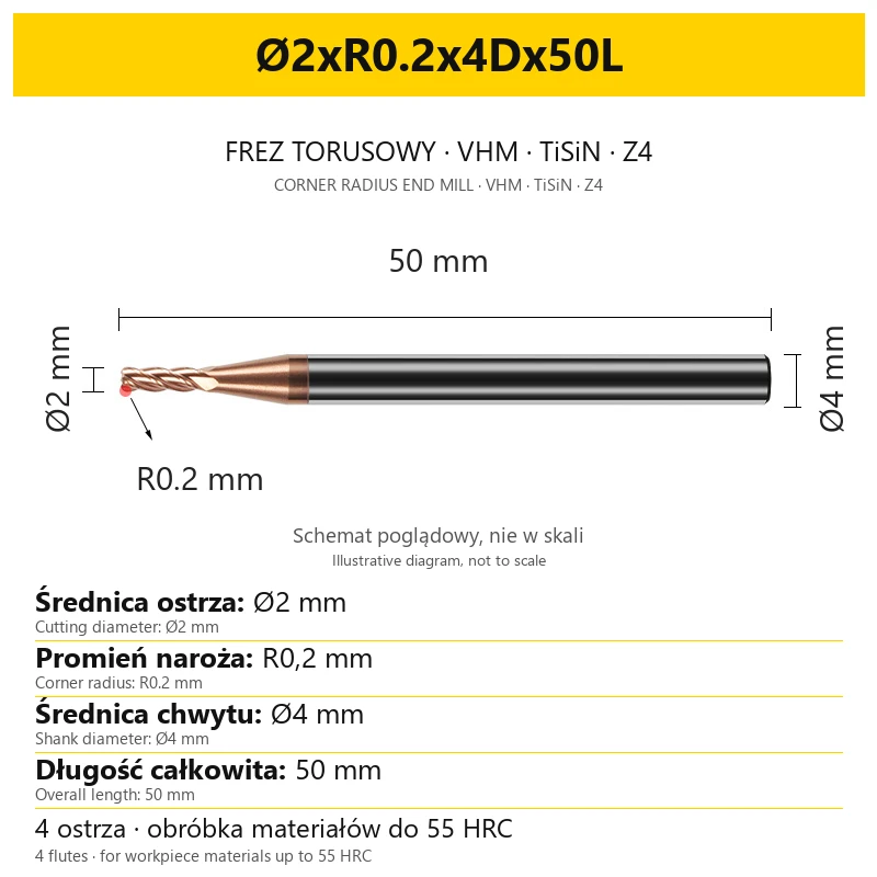
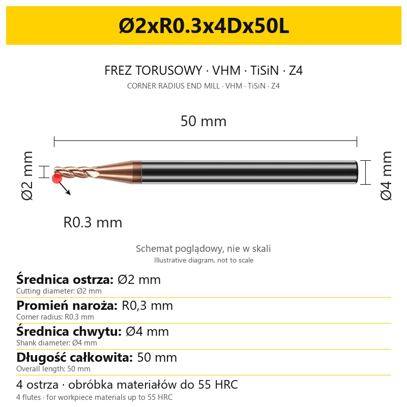
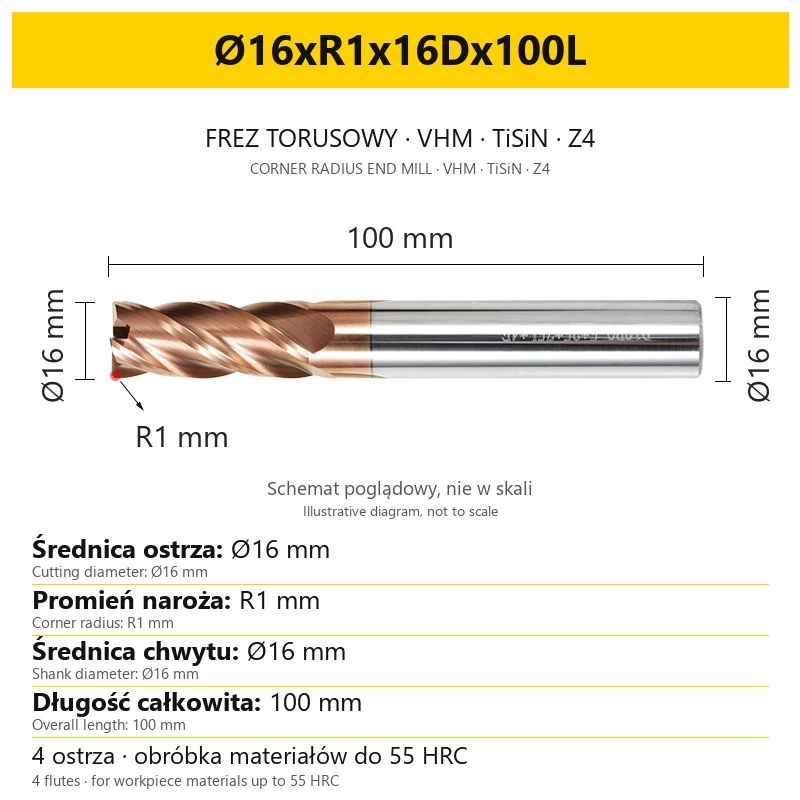
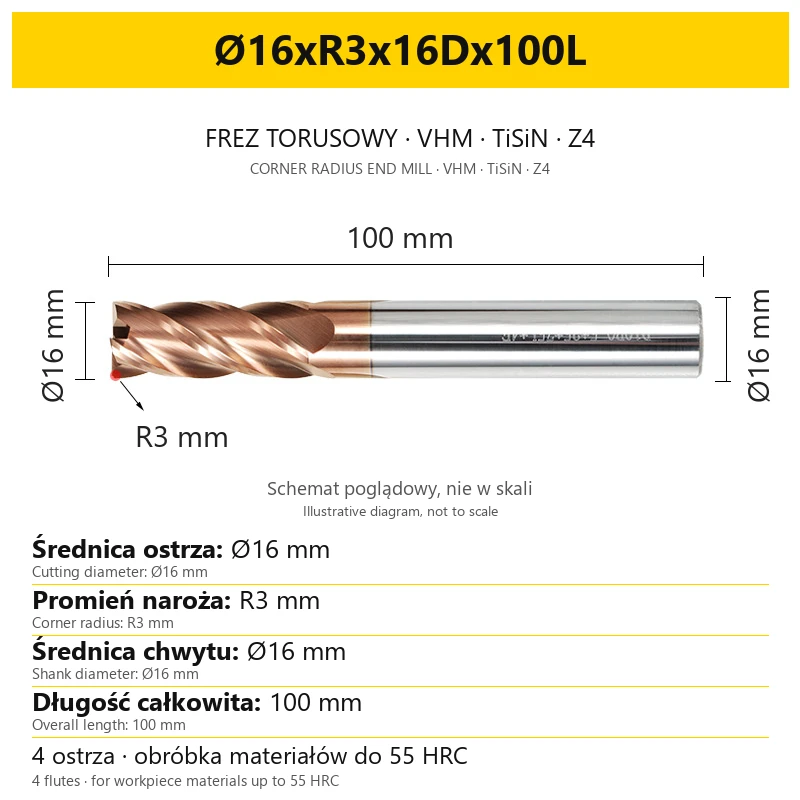
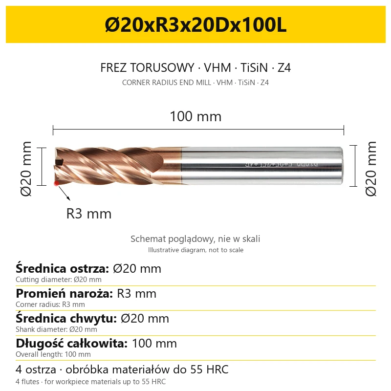
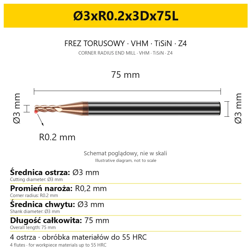
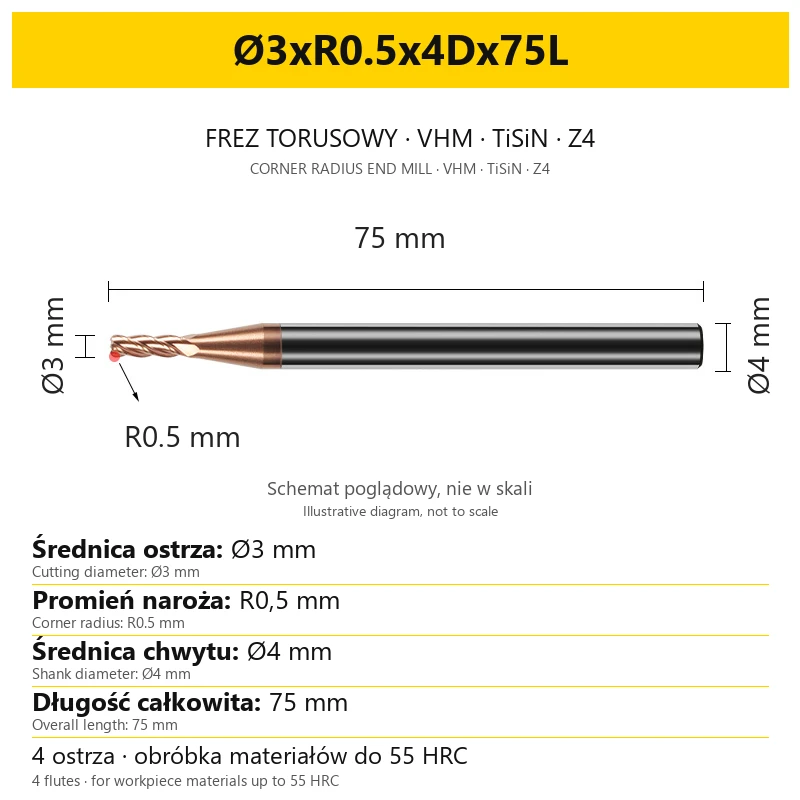
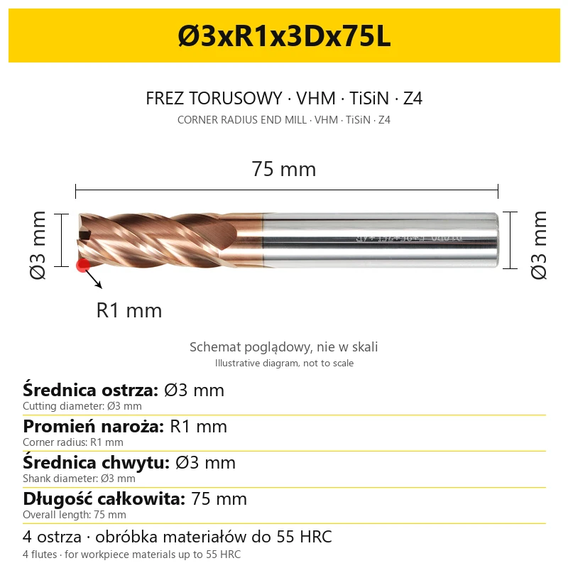
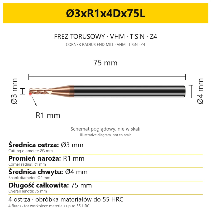
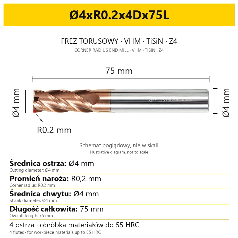
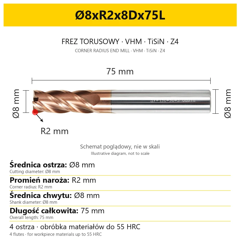
Example: Ø8xR2x8Dx60L. Each of the four elements describes a different dimension; all values are in millimetres.
| Designation | Meaning | Value in the example |
|---|---|---|
| Ø8 | Cutting diameter | 8 mm |
| R2 | Corner radius of the cutting part | 2 mm |
| 8D | Shank diameter clamped in the holder | 8 mm |
| 60L | Overall cutter length | 60 mm |
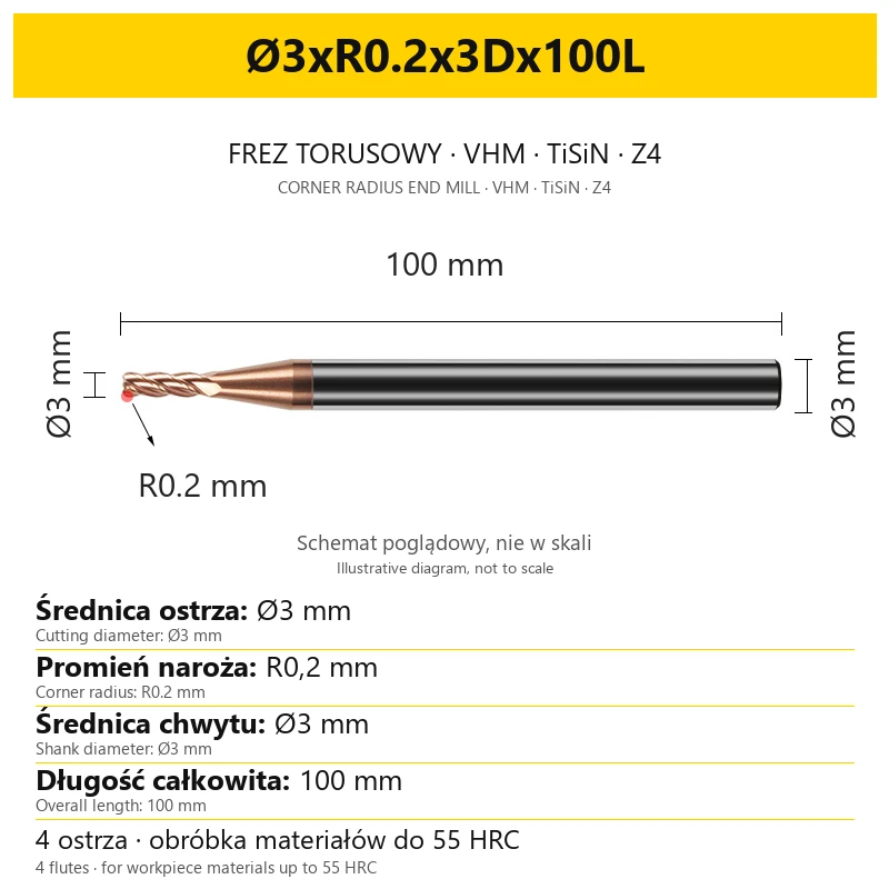
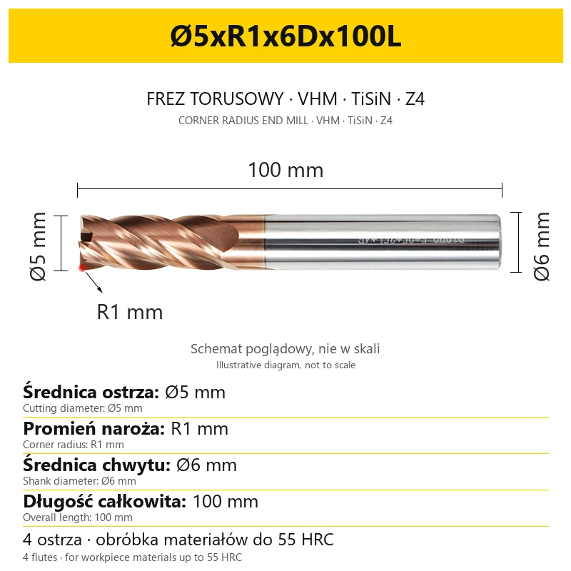
In this listing's designations, the letter D in the third value refers to the shank. The symbol Ø at the start refers to the cutting part. These diameters may differ, so holder selection requires checking the complete code.
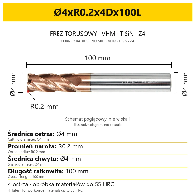
Dimensional graphics are illustrative and are not scale drawings. Use dimension values and the variant designation for selection.
5. Selecting diameter, radius and length
- Cutting diameter. Compare it with slot width, pocket size and access to the machined contour. Choose a size appropriate to the part geometry.
- Corner radius R. Check the required rounding on the drawing and how the corner works in the planned operation. Variants with the same diameter but a different R have different corner geometry.
- Shank diameter. Match the dimension ending in D to the holder. For example, variant Ø1xR0.2x4Dx50L has a Ø1 mm cutting part and a Ø4 mm shank.
- Overall length. Select the reach needed for the operation, taking account of the holder and access to the part. A longer cutter requires checking clamping conditions.
- Complete operation geometry. Before machining, check working-part length, wall access and clearance for the holder. The required depth does not follow from the L designation alone.
6. Clamping and use of extended versions
The cutter is intended for use on a milling machine or machining centre with suitable tool and workpiece clamping. Before machining, check the condition of the shank, holder and cutting edges.
- Keep projection length as short as possible. Extend the tool only as far as needed to reach the machining area.
- Check clamping and runout. The shank and holder surfaces should be clean. Check the clamped cutter before starting the program.
- Adapt load to tool length. Long projection affects system rigidity and therefore requires separate selection of cutting conditions.
- Monitor the machining process. If vibration or unusual noise occurs, stop work, check the clamping and flutes, and correct conditions before restarting.
Select speed, feed, depth and width of cut for the material grade and hardness, cutter diameter, operation type and actual projection length. A 150L or 200L version requires its length to be considered in process settings.
7. What the order includes
| Item | Scope |
|---|---|
| Sales unit | 1 VHM TiSiN corner radius end mill, 4-flute |
| Selected size | Variant defined by cutting diameter, radius R, shank diameter and overall length |
| Quantity | Number of pieces of the selected variant stated in the order |
8. Frequently asked questions
What does radius R mean?
R is the corner-rounding radius of the cutting part. For example, R0.5 means a radius of 0.5 mm. It is a different parameter from the radius resulting from half the diameter of the entire cutter.
Is this a ball-nose end mill?
This is a corner radius end mill with a rounded corner. When programming machining, select the correct geometry type and enter the corner radius given in the variant designation.
Is the cutter suitable for stainless steel?
Yes, stainless steel is within the application range. Select cutting conditions for the material grade, operation and clamping rigidity.
Does 150L mean a 150 mm cutting-edge length?
150L means a 150 mm overall tool length. Working-part length and access to the machined surface must be checked separately.
Does the shank always have the same diameter as the cutting part?
The diameters may differ. Select the shank dimension for the holder, i.e. the value ending in D, rather than only the first number in the code.
What data should be provided when selecting a cutter?
Prepare the material grade and hardness, drawing or required part dimensions, operation type, planned projection length and clamping diameter. When working with a CAM program, also provide the required corner radius.
Related products
-
E006-379B3


Carbide Corner Rounding End Mill
-
0678-65504Bestseller


Carbide Corner Rounding End Mill - TiSiN Coated
-
A31B-1652FBestseller


Carbide T-Slot End Mill - TiSiN Coated
-
F6E0-701F2Bestseller
 2-Flute End Mills 0.00
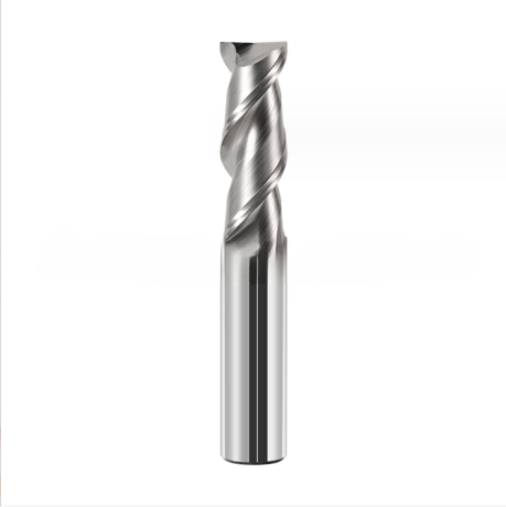
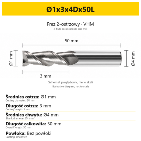
2-Flute Carbide End Mill for Aluminium
-
4405-36841Bestseller
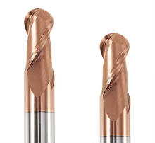 Ball Nose End Mills 0.00
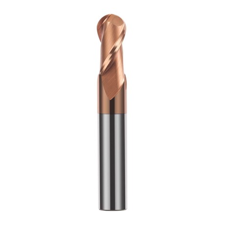
2-Flute TiSiN Coated Carbide Ball Nose End Mill
-
A31B-1652F_2Bestseller

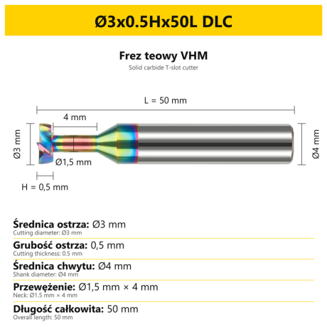
4-Flute Carbide T-Slot End Mill DLC


Bestsellers
-
Bestseller
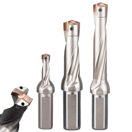
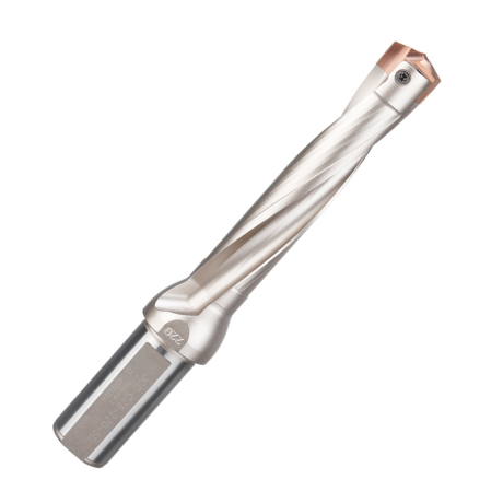
JCD modular drill with replaceable tip - internal cooling, for deep holes | GrotXD
JCD C20-100-3D Ø10~10.9 JCD C20-110-3D Ø11~11.9 JCD C20-120-3D Ø12~12.9 JCD C20-130-3D Ø13~13.9 JCD C20-140-3D Ø14~14.9 + 61 morePrice €69.86Price €56.79without VAT -
Bestseller
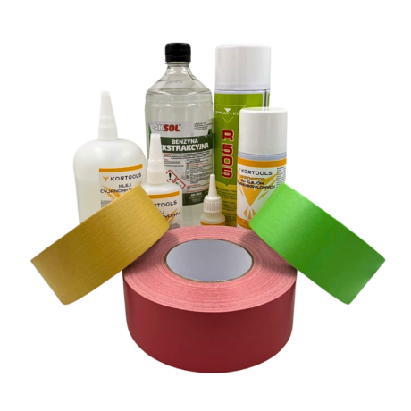
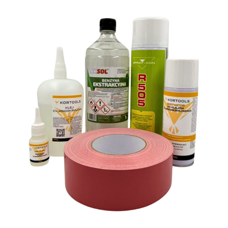
Kortools Adhesive + Tape CNC Workholding Kit
Yellow tape 5cm x 50m; adhesive 100g Yellow tape 5cm x 50m; adhesive 500g Yellow tape 10cm x 50m; adhesive 100g Yellow tape 10cm x 50m; adhesive 500g Green tape 5cm x 50m; adhesive 100g + 7 morePrice €44.66Price €36.31without VAT -
Price €17.18Price €13.97without VAT
-
Price €7.10Price €5.77without VAT
-
Price €7.56Price €6.14without VAT
-
Bestseller
 Other Accessories 0.00
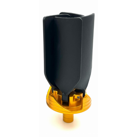
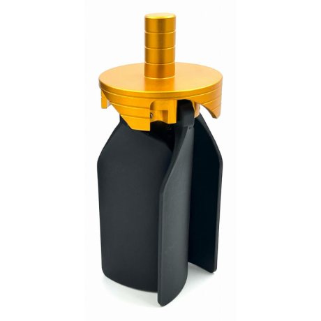
CNC Chip Fan / Chip Blower
Complete CNC chip fan Kit: blades, springs, pins and screwsPrice €53.82Price €43.76without VAT -
Bestseller
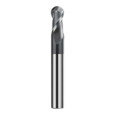
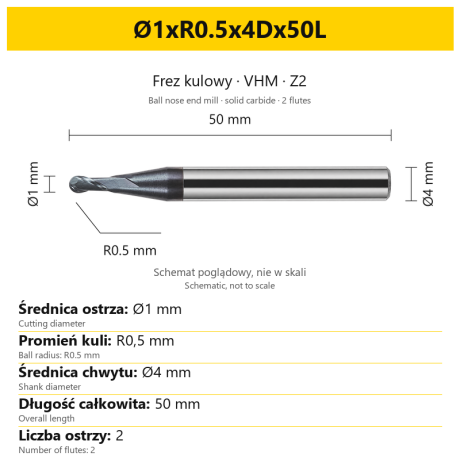 Ball Nose End Mills 0.00
2-Flute Carbide Ball Nose End Mill - HYPERCUT
Ø1xR0.5x4Dx50L Ø1.5xR0.75x4Dx50L Ø2xR1x4Dx50L Ø2.5xR1.25x4Dx50L Ø3xR1.5x3Dx50L + 26 morePrice €10.14Price €8.25without VAT -
Bestseller
2-Flute End Mills 0.00
2-Flute Carbide End Mill for Aluminium
Ø1x3x4Dx50L Ø1.5x4x4Dx50L Ø2x6x4Dx50L Ø2.5x7.5x4Dx50L Ø3x9x3Dx50L + 31 morePrice €5.35Price €4.35without VAT -
Bestseller
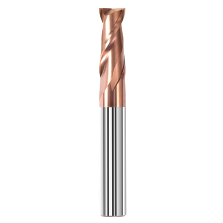
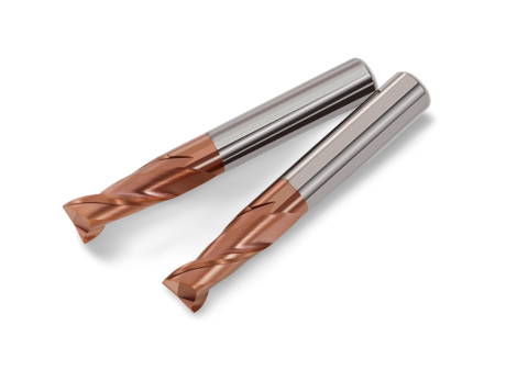 2-Flute End Mills 0.00
2-Flute Carbide End Mill for Steel 55 HRC - TiSiN - Solid Carbide
Ø6x24x6Dx75L Ø8x25x8Dx75L Ø4x20x4Dx100L Ø5x30x5Dx100L Ø6x30x6Dx100L + 31 morePrice €4.40Price €3.58without VAT -
Bestseller
 Ball Nose End Mills 0.00
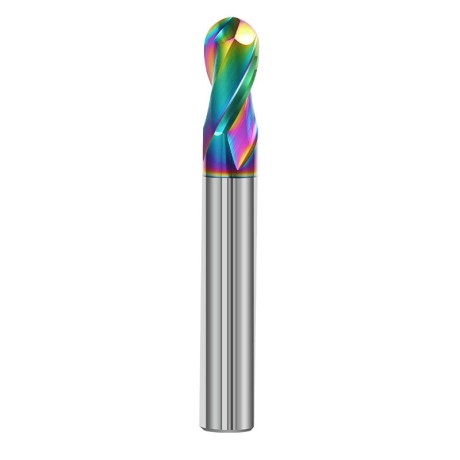
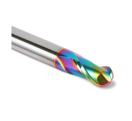
2-Flute DLC Coated Carbide Ball Nose End Mill| DuraEdge Alu
Ø1.0xR0.5x4Dx50L Ø1.5xR0.75x4Dx50L Ø2.0xR1x4Dx50L Ø2.5xR1.25x4Dx50L Ø3.0xR1.5x3Dx50L + 34 morePrice €7.89Price €6.41without VAT -
Bestseller
 2-Flute End Mills 0.00
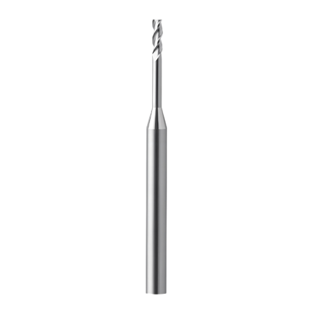
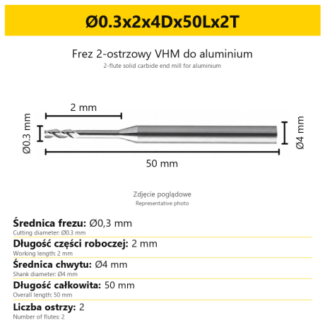
2-Flute End Mill for Aluminium | VHM | Miniature Ø0.3 - Ø0.9
Ø0.3x2x4Dx50Lx2T Ø0.3x3x4Dx50Lx2T Ø0.3x4x4Dx50Lx2T Ø0.4x2x4Dx50Lx2T Ø0.4x3x4Dx50Lx2T + 28 morePrice €7.99Price €6.50without VAT -
Bestseller
Ball Nose End Mills 0.00
2-Flute TiSiN Coated Carbide Ball Nose End Mill
Ø1xR0.5x4Dx50L Ø1.5xR0.75x4Dx50L Ø2xR1x4Dx50L Ø2.5xR1.25x4Dx50L Ø3xR1.5x3Dx50L + 38 morePrice €7.28Price €5.92without VAT -
Bestseller
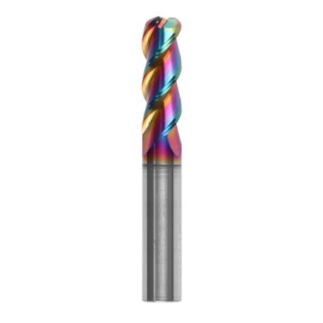
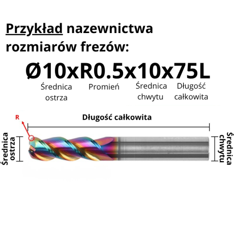
3-Flute Carbide Corner Radius End Mill for Aluminium| AL DLC
Ø1xR0.1x4Dx50L Ø1xR0.2x4Dx50L Ø1xR0.3x4Dx50L Ø1.5xR0.1x4Dx50L Ø1.5xR0.2x4Dx50L + 137 morePrice €4.96Price €4.04without VAT -
Bestseller
 3-Flute End Mills 0.00
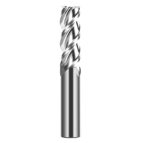
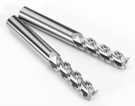
3-Flute Carbide End Mill VHM Z-3 for Aluminium| TriMill AL
Ø1x3xD4x50L Ø1.5x5x4Dx50L Ø2x6x4Dx50L Ø2.5x8x4Dx50L Ø3x9x3Dx50L + 41 morePrice €5.10Price €4.15without VAT -
Bestseller
 Countersinks 0.00
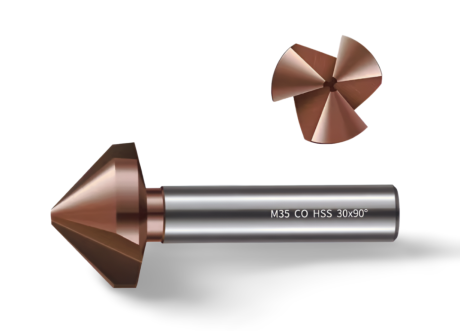
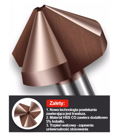
3-Flute Countersink Fi4.5-fi60, 90° - HSS-CO - 5% Kobaltu | Straight Shank
Ø4.5 x 4 x 90° x 40L Ø5 x 5 x 90° x 45L Ø6.3 x 5 x 90° x 45L Ø8.3 x 6 x 90° x 50L Ø10.4 x 6 x 90° x 50L + 12 morePrice €4.81Price €3.91without VAT -
Bestseller
 3-Flute End Mills 0.00
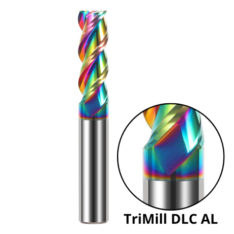
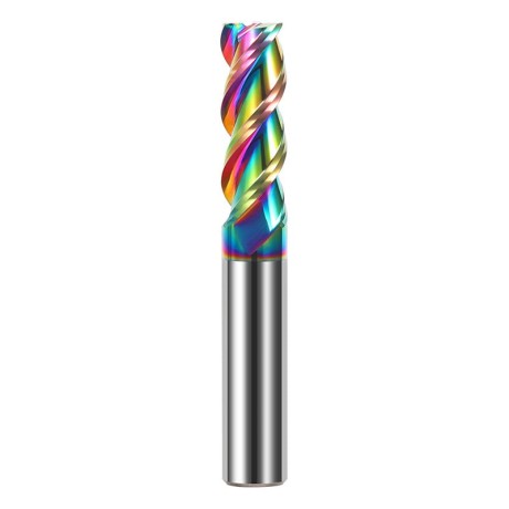
3-Flute DLC Coated Carbide End Mill | TriMill DLC AL
Ø1x3x4Dx50L Ø1.5x5x4Dx50L Ø2x6x4Dx50L Ø2.5x8x4Dx50L Ø3x8x3Dx50L + 38 morePrice €5.07Price €4.12without VAT