

55° Whitworth/BSW/BSF/BSP inch thread end mill for threading (pitch 1.377-2.540mm) - single edge, uncoated
Shipping costs are not included in the price.
Shipping costs are not included in the price.
Ask about the product

The administrator of personal data is Kortools. We process it to respond to your inquiry. More information regarding the processing of personal data can be found in privacy policy.
Select a product variant:
Individual variants may differ in price
Product code: 0613-367F8
Product description
Whitworth form • BSW / BSF / BSP • pitch P0.907–2.54 mm depending on variant
A solid carbide cutter for milling 55° threads on CNC machines. Its single axial thread form follows a helical tool path. Pitch is selected in the program within the range specified for the individual variant. The range also includes variants intended for one stated pitch.
Select the tool from the component drawing: check the thread standard and form angle, pitch, bore diameter and required reach. Numbers in the size code describe the cutter and its pitch range; the first number is not a nominal pipe-thread size. The selected variant card states cutting diameter, working length, shank diameter and overall length.
Construction and tool specification
| Parameter | Specification |
|---|---|
| Tool type | Thread mill with a single axial thread form |
| Tool material | VHM — solid carbide |
| Surface specification | Uncoated |
| Thread form angle | 55° |
| Thread family | Whitworth: BSW, BSF and BSP, subject to matching pitch and suitable component geometry |
| Pitch P | 0.907–2.54 mm across the range; the selected variant specifies a range or a single pitch |
| Shank | Cylindrical, Ø4–Ø12 mm depending on variant |
| Overall length | 50, 60 or 75 mm depending on size |
The single-form designation describes one thread-forming profile along the tool axis. It does not specify the number of circumferential flutes. Working length is the dimension of the working section and reach stated on the card; it does not mean a sequence of equally spaced teeth along that entire length.
Applications and workpiece materials
The uncoated version is intended for aluminium, copper and the other specified non-ferrous materials. Applications also include selected plastics. Choose the specification for the particular material and its condition, rather than cutter diameter alone.
| Material group | Application range |
|---|---|
| Aluminium | Aluminium profiles and aluminium alloys. |
| Copper and brass | Copper and copper alloys, including brass. |
| Zinc and magnesium alloys | Thread milling with cutting conditions adapted to the material. |
| Plastics | Selected plastics, including phenolic materials; select conditions for the particular plastic. |
Do not transfer parameters from another size or surface specification without checking the machining conditions. Consider tool overhang, runout, access to the thread and space for chips. Longer overhang reduces the rigidity of the tool setup.
55° threads and pitch selection
The 55° form angle belongs to the Whitworth family. G and PF are parallel pipe-thread designations; Rc and PT are designations associated with tapered pipe threads. They are not metric M thread designations. Select BSW, BSF and BSP threads by the applicable standard, diameter and pitch.
Metric M, UNC, UNF and NPT threads use a different form angle of 60°. Do not select this cutter for those threads solely because a pitch value falls within its range. Matching pitch alone does not establish profile compatibility. For a tapered thread, the program must also account for the required taper; the 55° angle does not create it automatically.
When the drawing specifies threads per inch, pitch in millimetres is calculated as P = 25.4 / TPI. The examples below are rounded to the notation used in the variants. Obtain the programmed value and inspection requirements from the thread documentation.
| Threads per inch | Pitch P in mm |
|---|---|
| 24 TPI | approximately 1.058 |
| 20 TPI | 1.27 |
| 19 TPI | approximately 1.337 |
| 14 TPI | approximately 1.814 |
How to read the size code
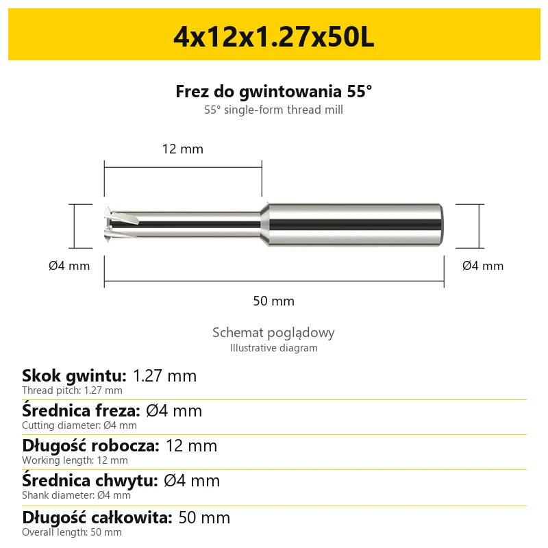
Example: 3.5x10x1.058x50L. The code states cutting diameter, working length, pitch or pitch range, and overall length, in that order. Linear dimensions are expressed in millimetres. A dot is the decimal separator.
| Code element | Meaning |
|---|---|
| 3.5 | Cutting diameter Ø3.5 mm |
| 10 | Working length 10 mm |
| 1.058 | Thread pitch 1.058 mm |
| 50L | Overall cutter length 50 mm |
The shank diameter of this example is Ø4 mm and is specified separately on the card. Do not substitute the first number in the code for shank diameter. Other sizes may show two pitch values separated by a hyphen. That range applies to the individual cutter, not to every cutter in this listing.
Dimensions and access to the thread
Cutting diameter defines the size of the cutting section. For an internal thread, the cutter must enter the prepared hole and have clearance to follow the required path. Do not confuse cutter diameter with nominal finished-thread diameter or the drill diameter used for the starting hole.
Working length helps assess the reach of the working section. Consider thread length, clearance to the bottom or other obstruction, entry and exit movements and the transition from the working section to the shank. No single card dimension is an unconditional maximum machining depth.
Shank diameter is used to select the holder, while overall length L specifies the length of the complete tool. Part of the shank remains inside the holder. A 50L, 60L or 75L designation does not mean a thread of that length. Keep overhang as short as possible while maintaining access to the machining area.
The range includes cutting diameters from Ø3.5 to Ø12 mm and working lengths from 10 to 35 mm, depending on the selected variant. The image on the card is illustrative. Read dimensions and pitch range from the labels assigned to the selected variant. The illustration is not a scale drawing and must not be used to measure tool proportions on screen.
Program and toolholding preparation
- Check the thread documentation. Identify the standard, 55° form, diameter, pitch, length and taper requirements where applicable.
- Select the correct variant. Confirm that the pitch is within its specified range and that diameter and reach suit the component.
- Prepare the holder. Clean the shank and clamping surfaces, inspect the cutting edges and check mounted tool runout.
- Verify the helical path. Check cutter diameter, movement direction, pitch, entry and exit, and clearance for the tool and holder.
A single thread form allows different pitches within the specified range because pitch is determined by the helical tool path. This does not permit exceeding the geometry limits stated for the cutter. Treat a variant with one stated pitch as intended for that value.
Operating conditions and thread inspection
Select spindle speed, feed and number of passes for the material, cutter diameter, edge load and setup rigidity. Reduce tool loading when using a long overhang. If vibration or unusual noise occurs, reduce the load and inspect toolholding and chip evacuation before continuing.
Select cooling, lubrication and chip removal for the particular metal or plastic. Keep the cutting area clear of accumulated chips and monitor edge condition during the first components.
Inspect the first finished thread using the method specified for the component, for example the appropriate GO and NO-GO gauges. Gauge selection follows the standard and tolerance of the finished thread. The tool description does not replace inspection or declare a tolerance class for every possible operation.
Frequently asked questions
Can one variant machine several pitches?
Yes, if a pitch range is specified. Select a value within that range and program the matching helical path. A variant with one pitch value is intended for that value.
Does 55° mean a metric thread?
No. It is the Whitworth family form angle. Standard metric M threads use a 60° angle.
Does single-form mean one flute?
It describes a single axial thread-forming profile in this listing. It does not specify the number of circumferential flutes.
Does overall length specify threading depth?
No. Assess usable reach together with working length, toolholding, entry and exit movements and component geometry.
Bestsellers
-
Bestseller
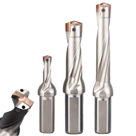
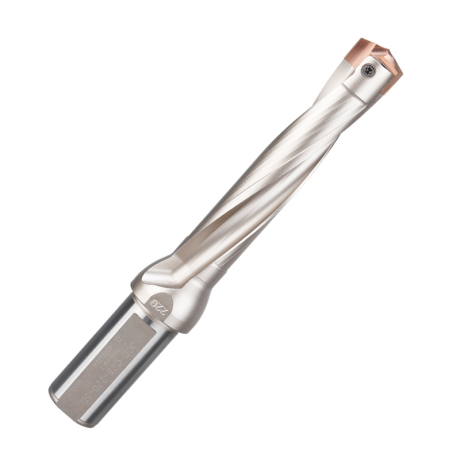
JCD modular drill with replaceable tip - internal cooling, for deep holes | GrotXD
JCD C20-100-3D Ø10~10.9 JCD C20-110-3D Ø11~11.9 JCD C20-120-3D Ø12~12.9 JCD C20-130-3D Ø13~13.9 JCD C20-140-3D Ø14~14.9 + 61 morePrice €69.86Price €56.79without VAT -
Bestseller
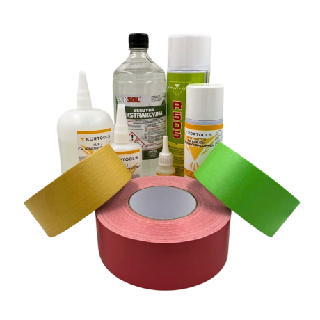
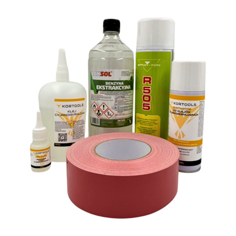
Kortools Adhesive + Tape CNC Workholding Kit
Yellow tape 5cm x 50m; adhesive 100g Yellow tape 5cm x 50m; adhesive 500g Yellow tape 10cm x 50m; adhesive 100g Yellow tape 10cm x 50m; adhesive 500g Green tape 5cm x 50m; adhesive 100g + 7 morePrice €44.66Price €36.31without VAT -
Price €17.18Price €13.97without VAT
-
Price €7.10Price €5.77without VAT
-
Price €7.56Price €6.14without VAT
-
Bestseller
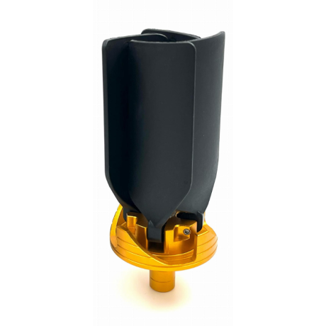
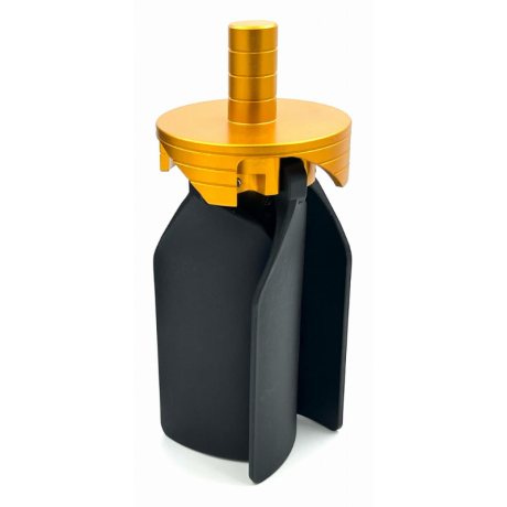 Other Accessories 0.00
CNC Chip Fan / Chip Blower
Complete CNC chip fan Kit: blades, springs, pins and screwsPrice €53.82Price €43.76without VAT -
Bestseller
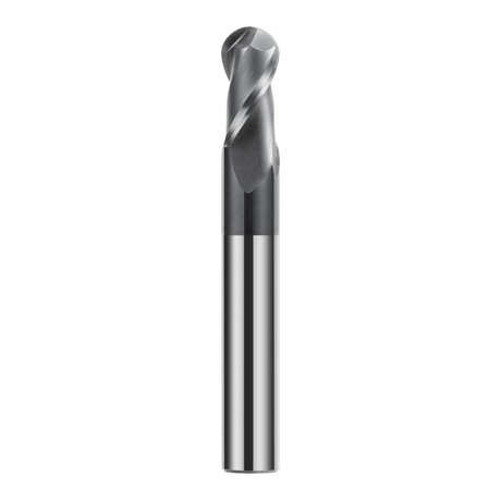
 Ball Nose End Mills 0.00
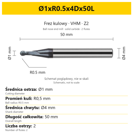
2-Flute Carbide Ball Nose End Mill - HYPERCUT
Ø1xR0.5x4Dx50L Ø1.5xR0.75x4Dx50L Ø2xR1x4Dx50L Ø2.5xR1.25x4Dx50L Ø3xR1.5x3Dx50L + 26 morePrice €10.14Price €8.25without VAT -
Bestseller
 2-Flute End Mills 0.00
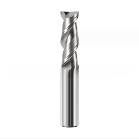
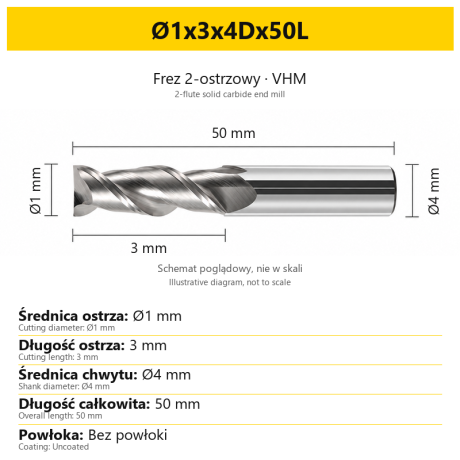
2-Flute Carbide End Mill for Aluminium
Ø1x3x4Dx50L Ø1.5x4x4Dx50L Ø2x6x4Dx50L Ø2.5x7.5x4Dx50L Ø3x9x3Dx50L + 31 morePrice €5.35Price €4.35without VAT -
Bestseller
 2-Flute End Mills 0.00
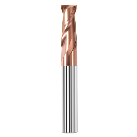
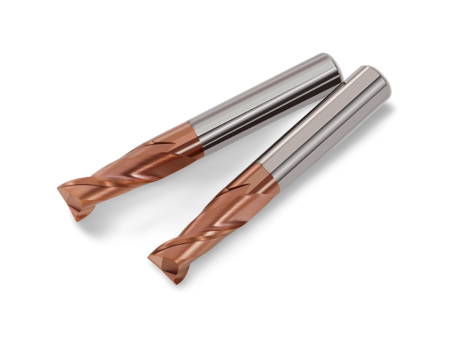
2-Flute Carbide End Mill for Steel 55 HRC - TiSiN - Solid Carbide
Ø6x24x6Dx75L Ø8x25x8Dx75L Ø4x20x4Dx100L Ø5x30x5Dx100L Ø6x30x6Dx100L + 31 morePrice €4.40Price €3.58without VAT -
Bestseller
 Ball Nose End Mills 0.00
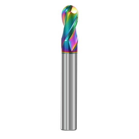
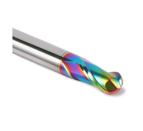
2-Flute DLC Coated Carbide Ball Nose End Mill| DuraEdge Alu
Ø1.0xR0.5x4Dx50L Ø1.5xR0.75x4Dx50L Ø2.0xR1x4Dx50L Ø2.5xR1.25x4Dx50L Ø3.0xR1.5x3Dx50L + 34 morePrice €7.89Price €6.41without VAT -
Bestseller
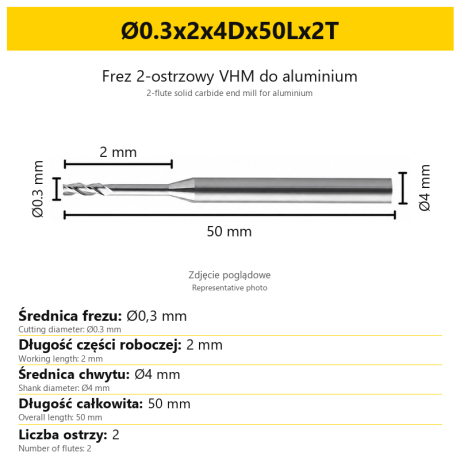 2-Flute End Mills 0.00
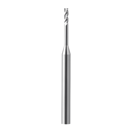
2-Flute End Mill for Aluminium | VHM | Miniature Ø0.3 - Ø0.9
Ø0.3x2x4Dx50Lx2T Ø0.3x3x4Dx50Lx2T Ø0.3x4x4Dx50Lx2T Ø0.4x2x4Dx50Lx2T Ø0.4x3x4Dx50Lx2T + 28 morePrice €7.99Price €6.50without VAT -
Bestseller
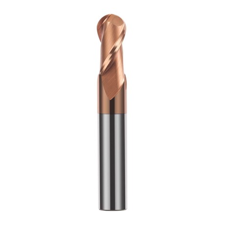
 Ball Nose End Mills 0.00
2-Flute TiSiN Coated Carbide Ball Nose End Mill
Ø1xR0.5x4Dx50L Ø1.5xR0.75x4Dx50L Ø2xR1x4Dx50L Ø2.5xR1.25x4Dx50L Ø3xR1.5x3Dx50L + 38 morePrice €7.28Price €5.92without VAT -
Bestseller
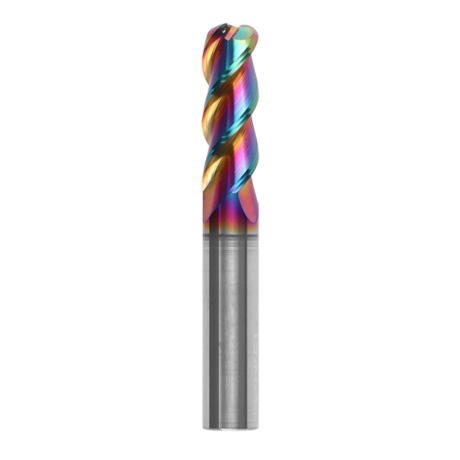
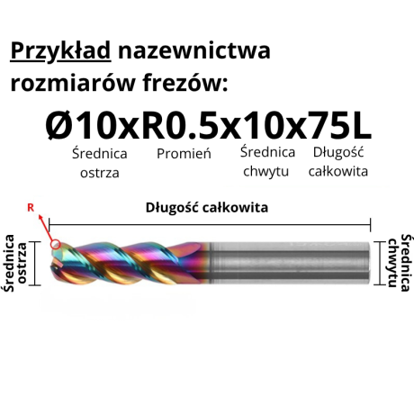
3-Flute Carbide Corner Radius End Mill for Aluminium| AL DLC
Ø1xR0.1x4Dx50L Ø1xR0.2x4Dx50L Ø1xR0.3x4Dx50L Ø1.5xR0.1x4Dx50L Ø1.5xR0.2x4Dx50L + 137 morePrice €4.96Price €4.04without VAT -
Bestseller
 3-Flute End Mills 0.00
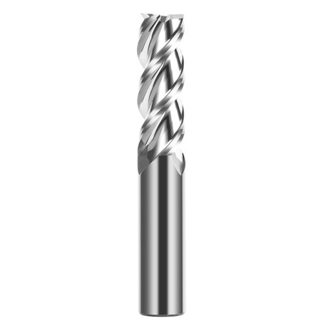
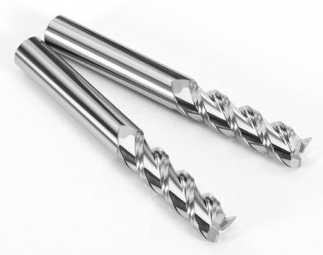
3-Flute Carbide End Mill VHM Z-3 for Aluminium| TriMill AL
Ø1x3xD4x50L Ø1.5x5x4Dx50L Ø2x6x4Dx50L Ø2.5x8x4Dx50L Ø3x9x3Dx50L + 41 morePrice €5.10Price €4.15without VAT -
Bestseller
 Countersinks 0.00
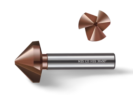
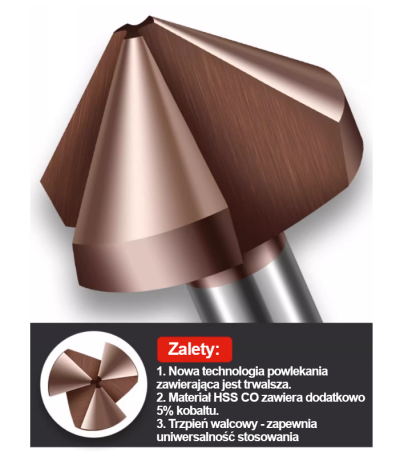
3-Flute Countersink Fi4.5-fi60, 90° - HSS-CO - 5% Kobaltu | Straight Shank
Ø4.5 x 4 x 90° x 40L Ø5 x 5 x 90° x 45L Ø6.3 x 5 x 90° x 45L Ø8.3 x 6 x 90° x 50L Ø10.4 x 6 x 90° x 50L + 12 morePrice €4.81Price €3.91without VAT -
Bestseller
 3-Flute End Mills 0.00
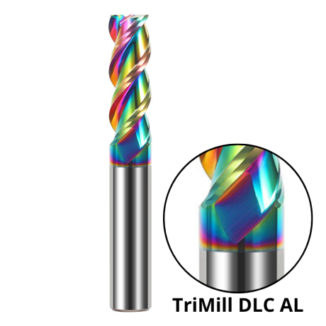
3-Flute DLC Coated Carbide End Mill | TriMill DLC AL
Ø1x3x4Dx50L Ø1.5x5x4Dx50L Ø2x6x4Dx50L Ø2.5x8x4Dx50L Ø3x8x3Dx50L + 38 morePrice €5.07Price €4.12without VAT