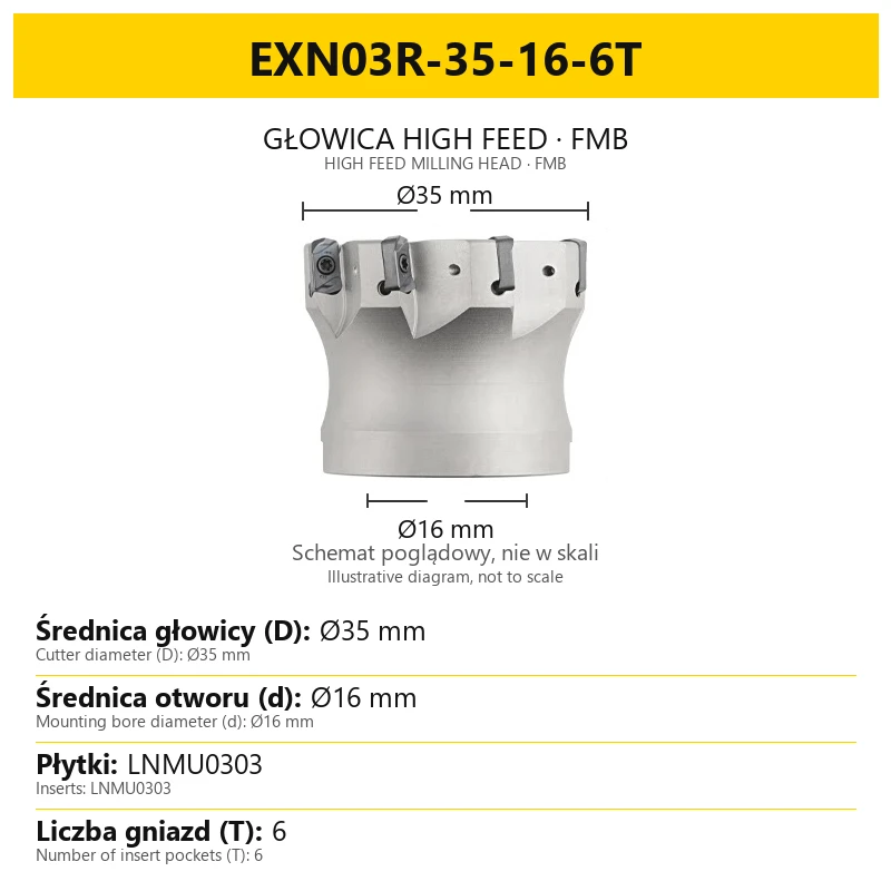
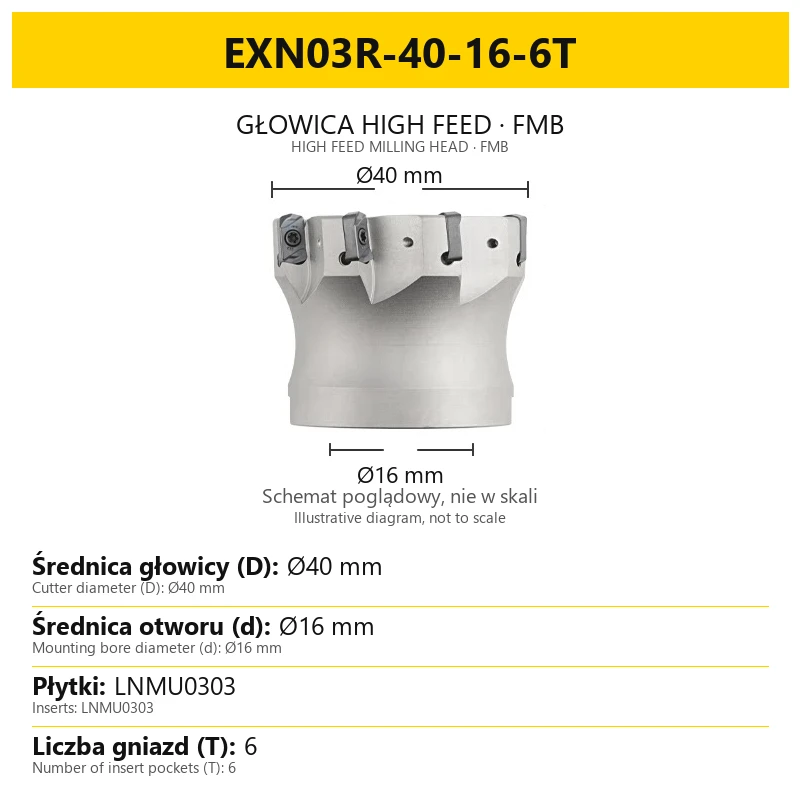
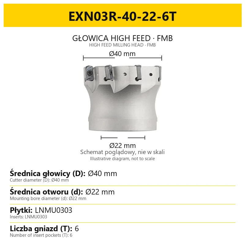
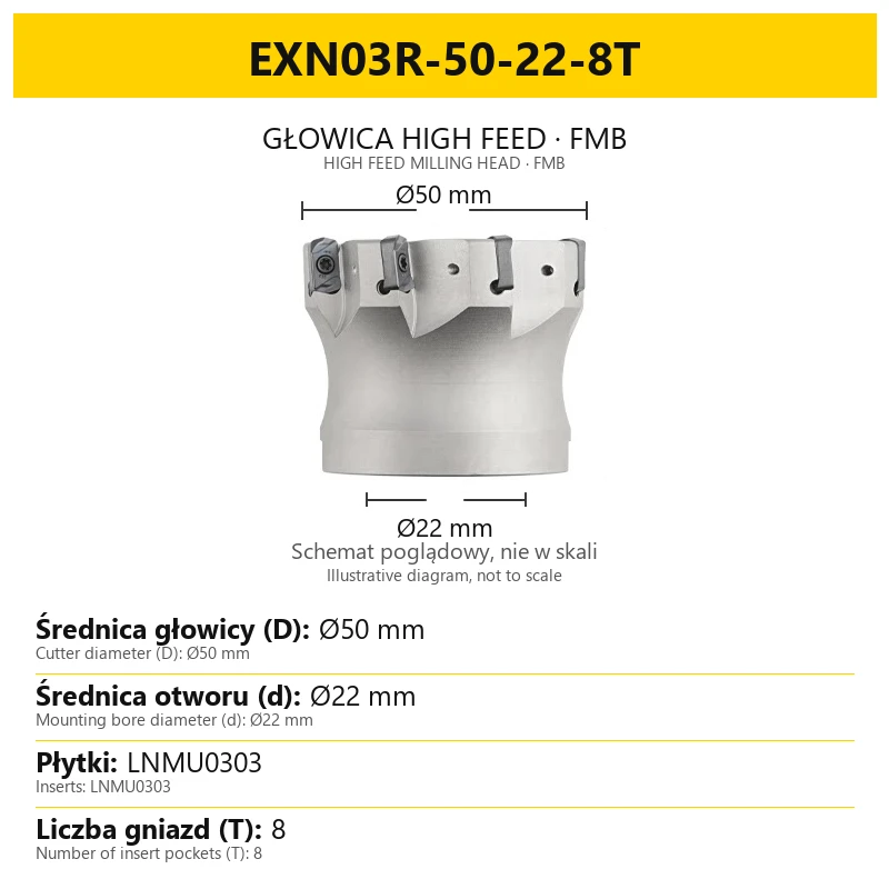
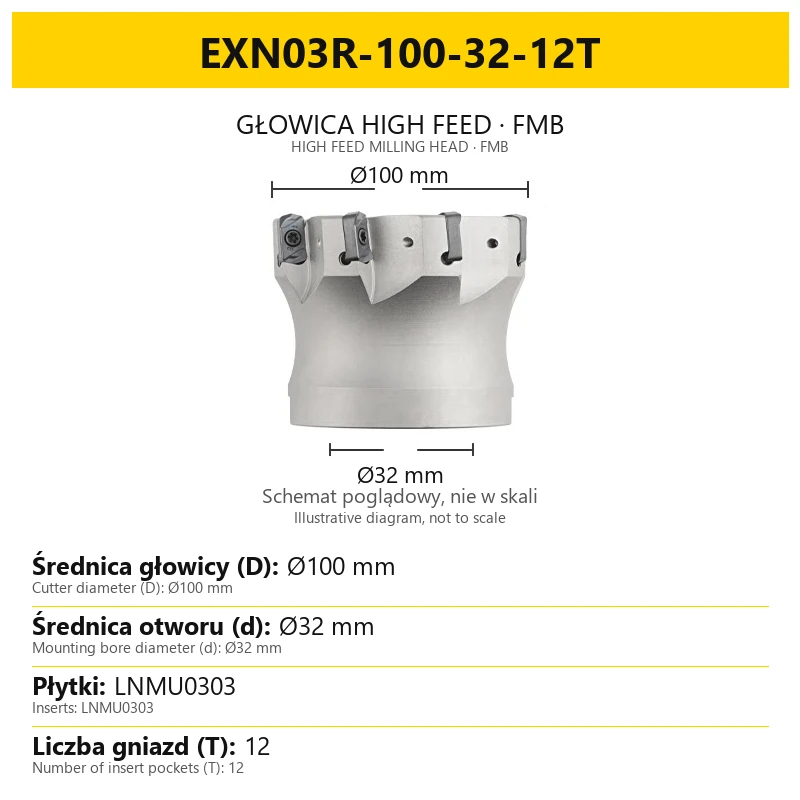


High Feed head - EXN03R for LNMU0303 inserts - FMB clip-on shank
Shipping costs are not included in the price.
Shipping costs are not included in the price.
Ask about the product

The administrator of personal data is Kortools. We process it to respond to your inquiry. More information regarding the processing of personal data can be found in privacy policy.
Select a product variant:
Individual variants may differ in price
Product code: F5CB-213DA
Product description
EXN03R High Feed Milling Head — LNMU0303 Inserts, FMB Mount
Rough machining · high feed rates · indexable inserts
EXN03R is a shell-mounted milling head for high feed roughing. It uses indexable LNMU0303 inserts to remove stock by the high feed method: shallow cuts with a suitable feed per tooth.
The 42CrMo steel body, with a hardness of 40–42 HRC, mounts on an FMB shell mill arbor. Select the cutter diameter, mounting bore diameter and number of insert pockets for your machining task and available holder.
1. How high feed milling works
High feed milling combines shallow cuts with high feed rates. The insert setting geometry promotes thin chips. This can allow a higher feed per tooth than many conventional operations, provided the conditions suit the insert and machining setup.
A greater proportion of the cutting force is directed along the tool axis towards the spindle. This can reduce lateral deflection at longer overhangs and assist stock removal in deeper pockets. Holder rigidity, workpiece clamping and effective chip evacuation remain important.
2. Applications and workpiece selection
- Stock removal and rough milling — high feed machining with shallow passes.
- Pocket machining — removing material within the accessible machining space; for deeper pockets, consider holder reach and chip evacuation.
- Machining at longer overhangs — using the high feed force direction with the most rigid practical setup.
- Plunge milling — only after verifying the permitted entry method and conditions for the selected cutter–insert combination and preparing a suitable CAM strategy.
Select the workpiece application through the grade and geometry of the LNMU0303 insert. The body designation alone does not specify an insert coating, chipbreaker or maximum workpiece hardness. For selection, provide the material grade, hardness, clamping conditions and planned operation.
3. Technical specifications
| Parameter | Value |
|---|---|
| Tool type | Shell-mounted high feed milling head for rough machining |
| Series | EXN03R |
| Inserts | LNMU0303; geometry designation in the series: LNMU0303ZER |
| Body material | 42CrMo steel |
| Body hardness | 40–42 HRC |
| Mounting | Shell mount on an FMB arbor |
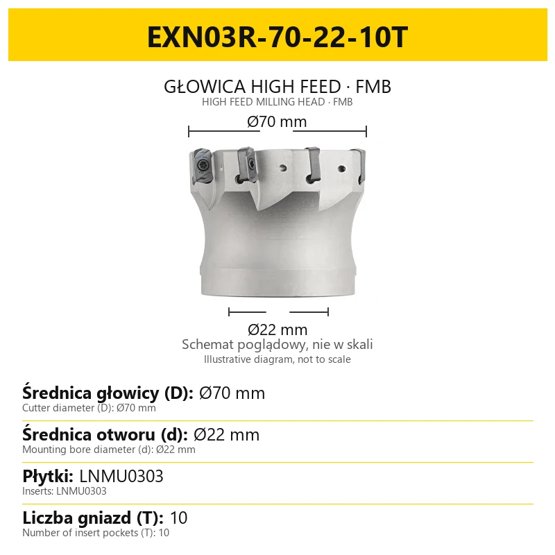
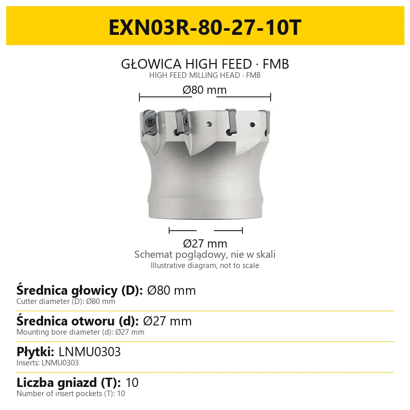
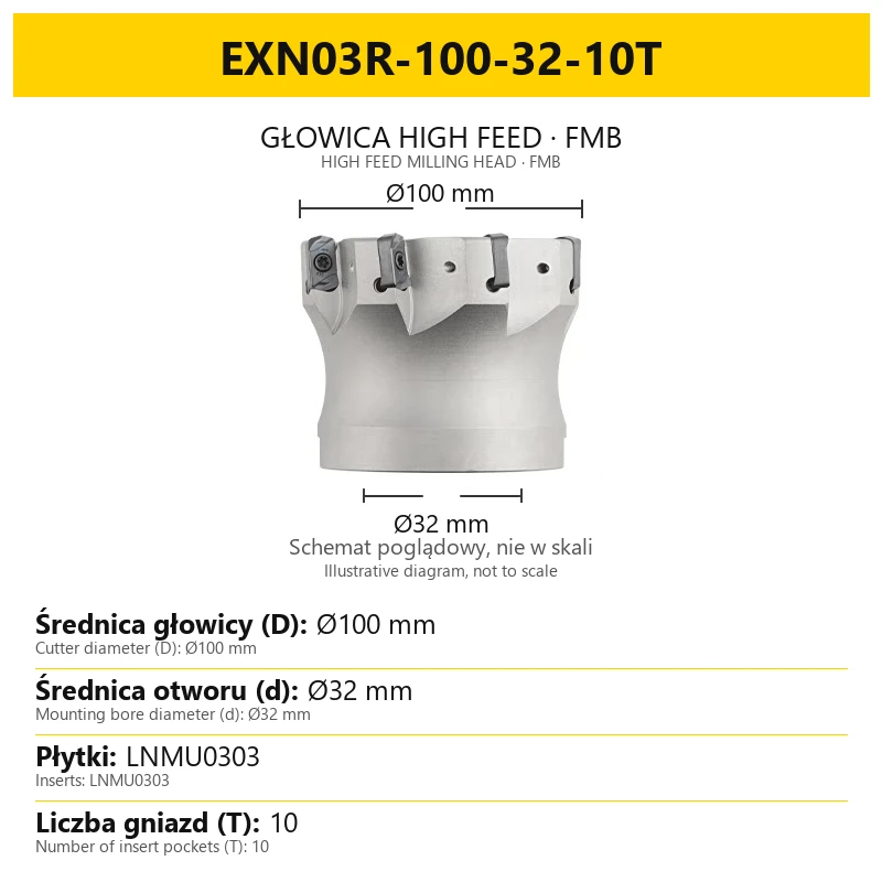
| Cutter diameter D | Ø35–100 mm, depending on the size |
| Mounting bore diameter d | Ø16, Ø22, Ø27 or Ø32 mm, depending on the size |
| Number of insert pockets | 6, 8, 10 or 12, depending on the size |
| Edges per LNMU0303ZER insert | 4 usable cutting edges |
4. Size designation and FMB mounting
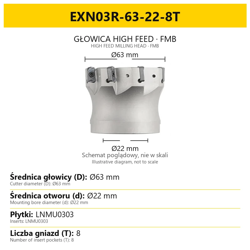
Example designation: EXN03R-63-22-8T. Its elements specify:
| Designation element | Meaning | Value in this example |
|---|---|---|
| EXN03R | Cutter series | High feed for LNMU0303 inserts |
| 63 | Cutter diameter D | Ø63 mm |
| 22 | Mounting bore diameter d | Ø22 mm |
| 8T | Number of cutter pockets / teeth | 8 |
FMB denotes shell mounting. Match the milling head to a suitable arbor using the mounting bore diameter. The bore diameter d, rather than the outer diameter D, determines the basic arbor fit.
Also check the drive arrangement, axial retention, reach and clearance of the complete assembly. The size designation does not specify holder length or the working length of the assembly.
5. LNMU0303 inserts and pocket count
Four edges per insert and the cutter tooth count are separate values. An LNMU0303ZER insert has four usable cutting edges. When the working edge wears, another edge can be used if the condition of the insert allows it.
8T denotes eight pockets in the body. A cutter with a complete set of inserts therefore has eight populated teeth. The four edges of one insert do not all cut simultaneously in a single pocket.
When selecting inserts, check the full designation, geometry, grade and application conditions. A correctly matched insert must seat without being forced and be secured according to the requirements of its fastening arrangement.
6. Selecting cutting conditions
Set speed and feed for the actual material, insert, diameter and setup rigidity. Monitor spindle load and chip formation, and assess changes in conditions through a machining trial.
Feed rate F = n × Z × fz, where n is spindle speed in rpm, Z is the number of effective cutting teeth, and fz is feed per tooth in mm/tooth. This relationship recalculates feed when speed or tooth count changes; it does not establish a permissible fz by itself.
Example for a Ø63 mm milling head:
| Parameter | Example value |
|---|---|
| Spindle speed n | 1000 rpm |
| Feed rate F | 6000 mm/min |
| Depth of cut ap | 0.8 mm |
| Width of cut ae | 50 mm |
| Cooling in this example | Dry or compressed air |
The example uses dry machining or compressed air. Select cooling and chip evacuation for the material and the recommendations for your insert. Do not interpret this example as a prohibition on coolant in every application.
7. Setup and machining practice
- Check the body and pockets. Remove chips and contamination from seating surfaces. Inspect the inserts and their fastening components.
- Check the holder assembly. Match the mounting diameter, secure the head correctly and keep overhang to the minimum needed for the operation.
- Prepare the toolpath. Consider entry, exit, changes in engagement at corners, and clearance for the head and holder. Plunge milling requires a separate strategy check.
- Provide chip evacuation. In pockets, check that chips do not accumulate in the cutting zone and get recut.
- Plan rough stock removal and finishing separately. Select the head primarily for high feed machining; account for surface and accuracy requirements in the subsequent machining strategy.
8. Questions and videos
Does 8T mean eight edges per insert?
No. It means eight pockets / teeth in the body. An LNMU0303ZER insert has four usable cutting edges.
Is the head only for workpieces at 40–42 HRC?
No. This is the body hardness. Suitability for the workpiece material and hardness depends on the selected insert and process conditions.
Do all Ø63 mm heads fit the same arbor?
The outer cutter diameter is not sufficient for selection. Check the mounting bore diameter and mounting design; in the example designation, the Ø63 mm head has a Ø22 mm bore.
Can the 6000 mm/min example be used for every size?
No. Feed depends on spindle speed, effective tooth count and permissible fz, among other factors. The example does not specify every machining condition.
What information is needed to select a head and inserts?
Provide the workpiece material and hardness, machining area dimensions, available FMB mounting, required reach, machine and planned stock removal strategy.
Videos — an illustrative machining demonstration
The videos help show the working method. Select conditions separately for your own machine, material, insert and setup.
Related products
-
3F7F-1158CBestseller
 Milling Inserts 5.00
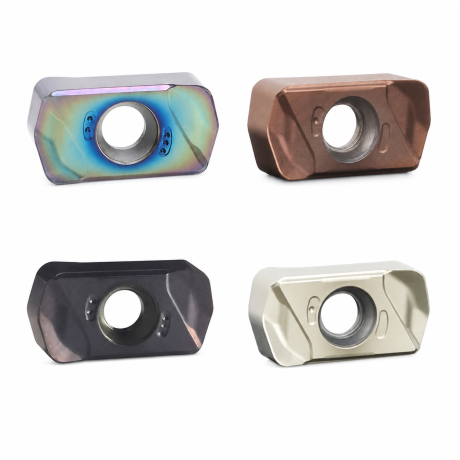
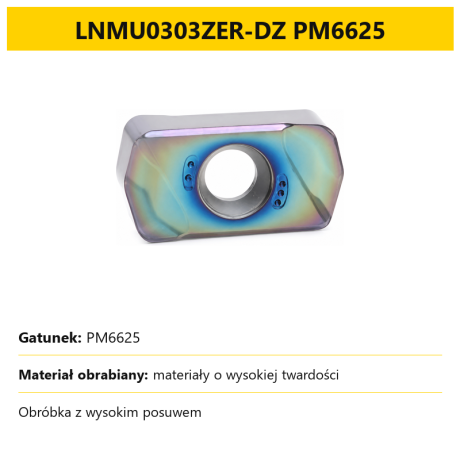
High Feed Milling Inserts LNMU 0303ZER | Wear Resistant LNMU0303
-
3382-7997EBestseller


High Feed EXN03R head for LNMU0303 inserts - cylindrical shank


Bestsellers
-
Bestseller
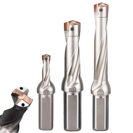
JCD modular drill with replaceable tip - internal cooling, for deep holes | GrotXD
JCD C20-100-3D Ø10~10.9 JCD C20-110-3D Ø11~11.9 JCD C20-120-3D Ø12~12.9 JCD C20-130-3D Ø13~13.9 JCD C20-140-3D Ø14~14.9 + 61 morePrice €69.86Price €56.79without VAT -
Bestseller
Kortools Adhesive + Tape CNC Workholding Kit
Yellow tape 5cm x 50m; adhesive 100g Yellow tape 5cm x 50m; adhesive 500g Yellow tape 10cm x 50m; adhesive 100g Yellow tape 10cm x 50m; adhesive 500g Green tape 5cm x 50m; adhesive 100g + 7 morePrice €44.66Price €36.31without VAT -
Price €17.18Price €13.97without VAT
-
Price €7.10Price €5.77without VAT
-
Price €7.56Price €6.14without VAT
-
Bestseller
 Other Accessories 0.00
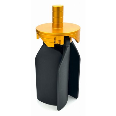
CNC Chip Fan / Chip Blower
Complete CNC chip fan Kit: blades, springs, pins and screwsPrice €53.82Price €43.76without VAT -
Bestseller
 Ball Nose End Mills 0.00
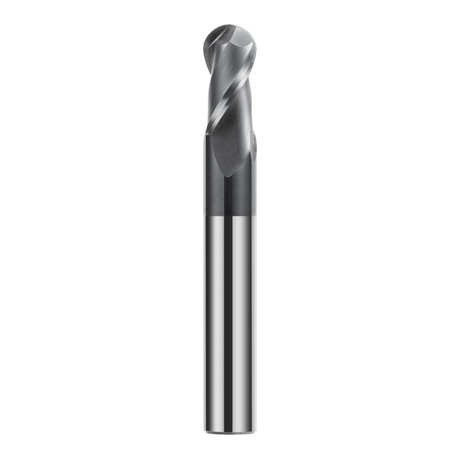
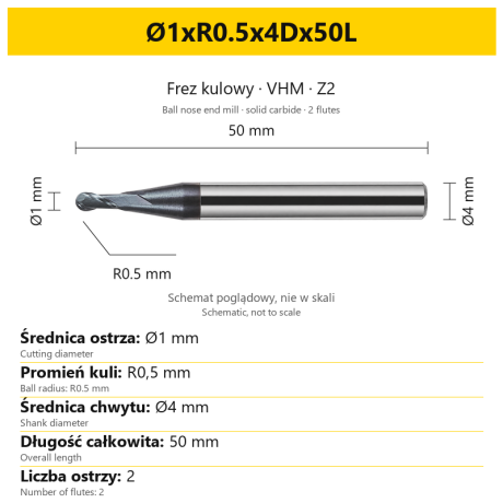
2-Flute Carbide Ball Nose End Mill - HYPERCUT
Ø1xR0.5x4Dx50L Ø1.5xR0.75x4Dx50L Ø2xR1x4Dx50L Ø2.5xR1.25x4Dx50L Ø3xR1.5x3Dx50L + 26 morePrice €10.14Price €8.25without VAT -
Bestseller
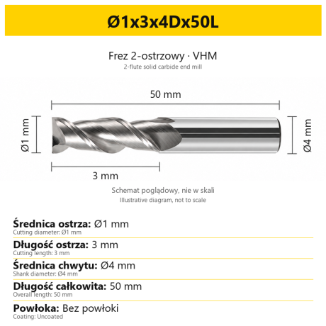 2-Flute End Mills 0.00
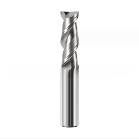
2-Flute Carbide End Mill for Aluminium
Ø1x3x4Dx50L Ø1.5x4x4Dx50L Ø2x6x4Dx50L Ø2.5x7.5x4Dx50L Ø3x9x3Dx50L + 31 morePrice €5.35Price €4.35without VAT -
Bestseller
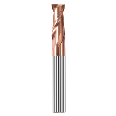
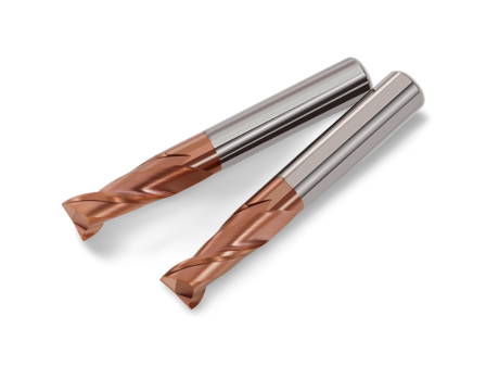 2-Flute End Mills 0.00
2-Flute Carbide End Mill for Steel 55 HRC - TiSiN - Solid Carbide
Ø6x24x6Dx75L Ø8x25x8Dx75L Ø4x20x4Dx100L Ø5x30x5Dx100L Ø6x30x6Dx100L + 31 morePrice €4.40Price €3.58without VAT -
Bestseller
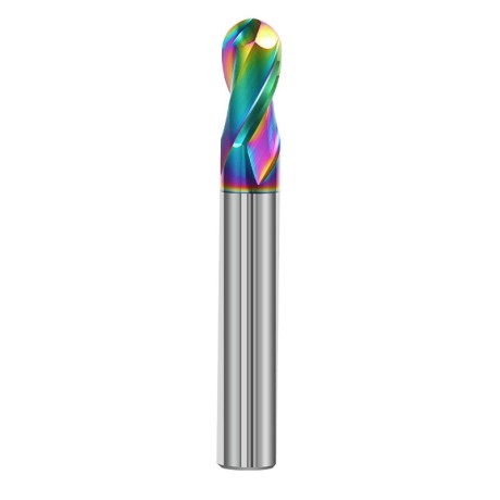
 Ball Nose End Mills 0.00
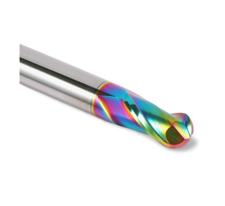
2-Flute DLC Coated Carbide Ball Nose End Mill| DuraEdge Alu
Ø1.0xR0.5x4Dx50L Ø1.5xR0.75x4Dx50L Ø2.0xR1x4Dx50L Ø2.5xR1.25x4Dx50L Ø3.0xR1.5x3Dx50L + 34 morePrice €7.89Price €6.41without VAT -
Bestseller
 2-Flute End Mills 0.00
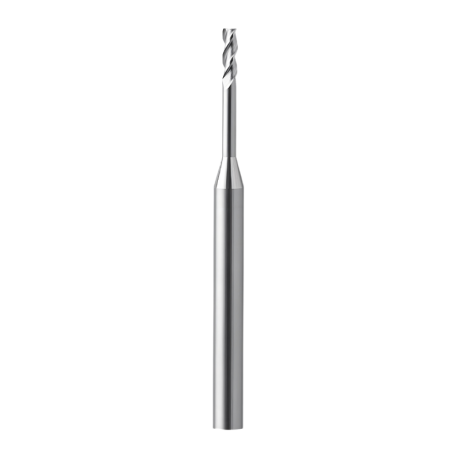
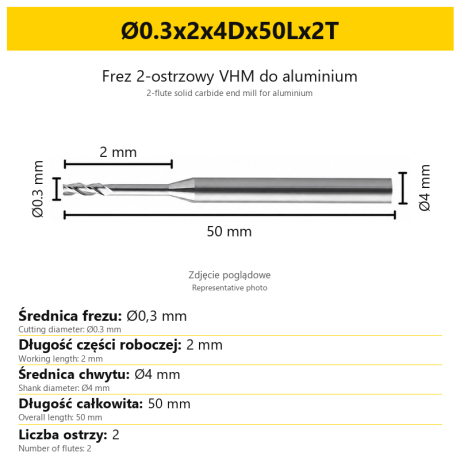
2-Flute End Mill for Aluminium | VHM | Miniature Ø0.3 - Ø0.9
Ø0.3x2x4Dx50Lx2T Ø0.3x3x4Dx50Lx2T Ø0.3x4x4Dx50Lx2T Ø0.4x2x4Dx50Lx2T Ø0.4x3x4Dx50Lx2T + 28 morePrice €7.99Price €6.50without VAT -
Bestseller
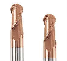 Ball Nose End Mills 0.00
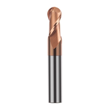
2-Flute TiSiN Coated Carbide Ball Nose End Mill
Ø1xR0.5x4Dx50L Ø1.5xR0.75x4Dx50L Ø2xR1x4Dx50L Ø2.5xR1.25x4Dx50L Ø3xR1.5x3Dx50L + 38 morePrice €7.28Price €5.92without VAT -
Bestseller
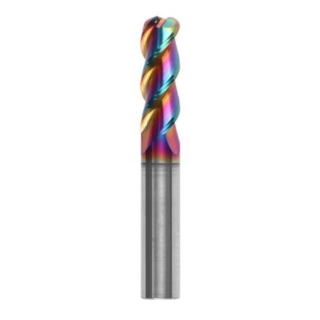
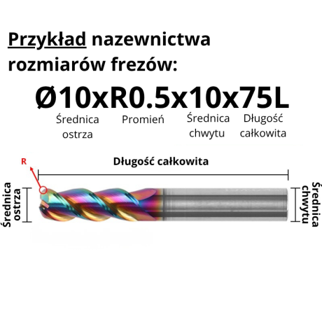
3-Flute Carbide Corner Radius End Mill for Aluminium| AL DLC
Ø1xR0.1x4Dx50L Ø1xR0.2x4Dx50L Ø1xR0.3x4Dx50L Ø1.5xR0.1x4Dx50L Ø1.5xR0.2x4Dx50L + 137 morePrice €4.96Price €4.04without VAT -
Bestseller
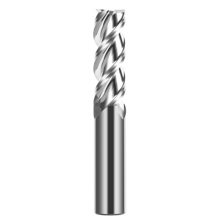
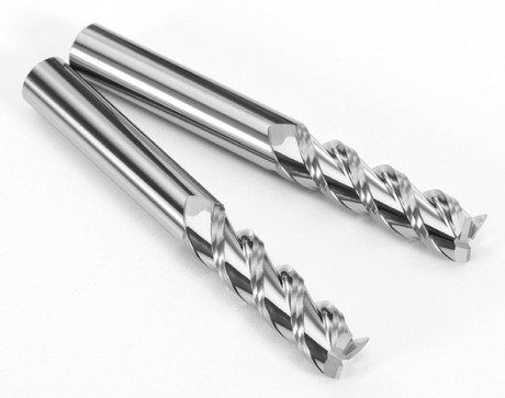 3-Flute End Mills 0.00
3-Flute Carbide End Mill VHM Z-3 for Aluminium| TriMill AL
Ø1x3xD4x50L Ø1.5x5x4Dx50L Ø2x6x4Dx50L Ø2.5x8x4Dx50L Ø3x9x3Dx50L + 41 morePrice €5.10Price €4.15without VAT -
Bestseller
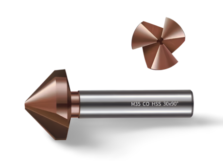
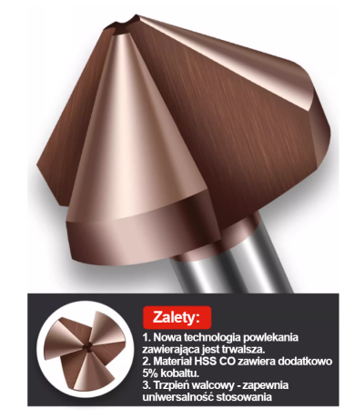 Countersinks 0.00
3-Flute Countersink Fi4.5-fi60, 90° - HSS-CO - 5% Kobaltu | Straight Shank
Ø4.5 x 4 x 90° x 40L Ø5 x 5 x 90° x 45L Ø6.3 x 5 x 90° x 45L Ø8.3 x 6 x 90° x 50L Ø10.4 x 6 x 90° x 50L + 12 morePrice €4.81Price €3.91without VAT -
Bestseller
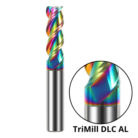
 3-Flute End Mills 0.00
3-Flute DLC Coated Carbide End Mill | TriMill DLC AL
Ø1x3x4Dx50L Ø1.5x5x4Dx50L Ø2x6x4Dx50L Ø2.5x8x4Dx50L Ø3x8x3Dx50L + 38 morePrice €5.07Price €4.12without VAT