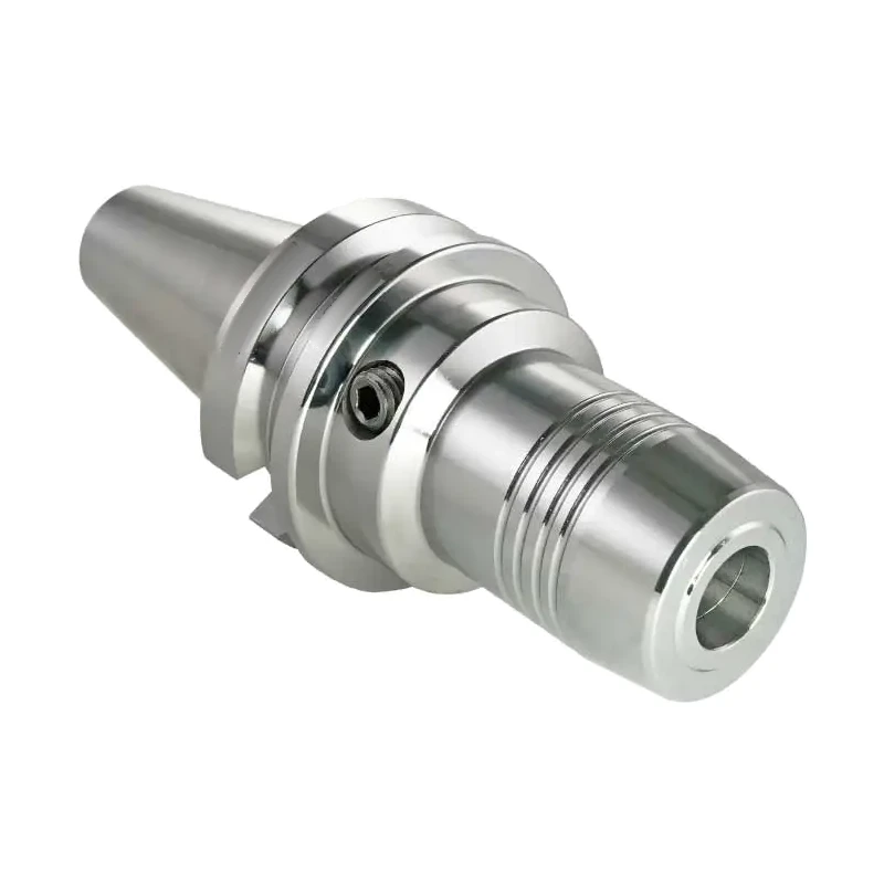
BT40 / BBT40 MAS 403 hydraulic chuck Ø6–32 mm
Shipping costs are not included in the price.
Shipping costs are not included in the price.

Weekly deals
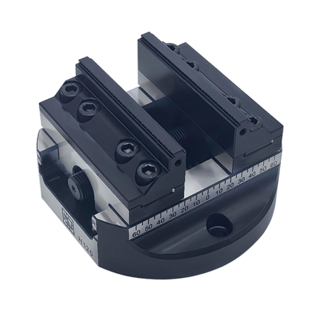
5-axis vise with hard jaws
Self-centering machine vise. Hard jaws included.
excl. VAT
Regular price:
Lowest price in the 30 days before the reduction:
Time left
Offer ends 06.11.2026 23:59. Offer applies to the vise + hard jaws bundle only.
Ask about the product

The administrator of personal data is Kortools. We process it to respond to your inquiry. More information regarding the processing of personal data can be found in privacy policy.
Select a product variant:
Individual variants may differ in price
Product code: EDD2-3525E
Product description
BT40 / BBT40 MAS 403 hydraulic chuck, Ø6–32 mm
Hydraulic chuck with a BT40 taper to MAS 403 BT (JIS B 6339). A cylindrical-shank tool is clamped directly in the chuck bore, without a collet: you tighten the clamping screw to the stop, and the oil in the chuck chamber expands the sleeve, which clamps the shank evenly around its full circumference (360°). The oil also dampens tool vibration. Grooves in the bore take up oil and grease residues from the shank, so the clamping surface stays dry.
A hex key for the clamping screw is needed to clamp and release the tool. No shrink fit unit or other device is required.
Available shank diameters: 6, 8, 10, 12, 14, 16, 18, 20, 25 and 32 mm. Length L = 90 mm (Ø25: 100 mm; Ø32: 105 mm) and extended versions L = 150 and 200 mm. Select the variant when purchasing.
Smaller shank diameters: a chuck Ø12, Ø20 or Ø32 can clamp a smaller tool through a hydraulic reduction sleeve (Ø12: shanks 3–8 mm; Ø20: shanks 3–16 mm; Ø32: shanks 6–25 mm). Sleeves are not included with the chuck — ask about availability.
Applications
- clamping end mills, drills, reamers and chamfering tools with cylindrical shanks
- precise machining: holder runout ≤ 0.003 mm, better hole accuracy in drilling and reaming, even cutting of all flutes in milling and less tool wear
- high clamping force and rigidity around the full circumference of the shank
- vibration damping by the oil in the chuck: smoother cutting and a better workpiece surface
- fast tool change with a hex key, no shrink fit unit needed
Specification
| Taper type | BT40 (MAS 403 BT / JIS B 6339) |
| Tool clamping | hydraulic: clamping screw and expansion sleeve with oil chamber |
| Tool shank diameter d | 6, 8, 10, 12, 14, 16, 18, 20, 25 or 32 mm (depending on variant) |
| Tool shank | cylindrical, diameter equal to d of the variant |
| Smaller shank diameters | with reduction sleeves for chucks Ø12, Ø20 and Ø32 (sleeves not included) |
| Length L | 90–200 mm (depending on variant) |
| Holder runout | ≤ 0.003 mm |
| Balance grade | at least G6.3 (many pieces are balanced to G2.5 at 25,000 rpm: ask us and we will check the label of the specific piece) |
| Coolant | AD version (central coolant supply) |
| Tool projection setting | stop screw with thread G in the bore (dimension table), adjustment range 10 mm |
| Tool clamping and release | hex key for the clamping screw |
| Standard | MAS 403 BT / JIS B 6339 (taper) |
Balance grade: at least G6.3. Many hydraulic chucks of this series are balanced to G2.5 at 25,000 rpm (more precise). If you need G2.5 for high spindle speeds, write to us before purchasing — we will check the label of the specific piece before shipping.
Coolant: AD version. If your spindle supplies coolant through the flange (form B), write to us before purchasing.
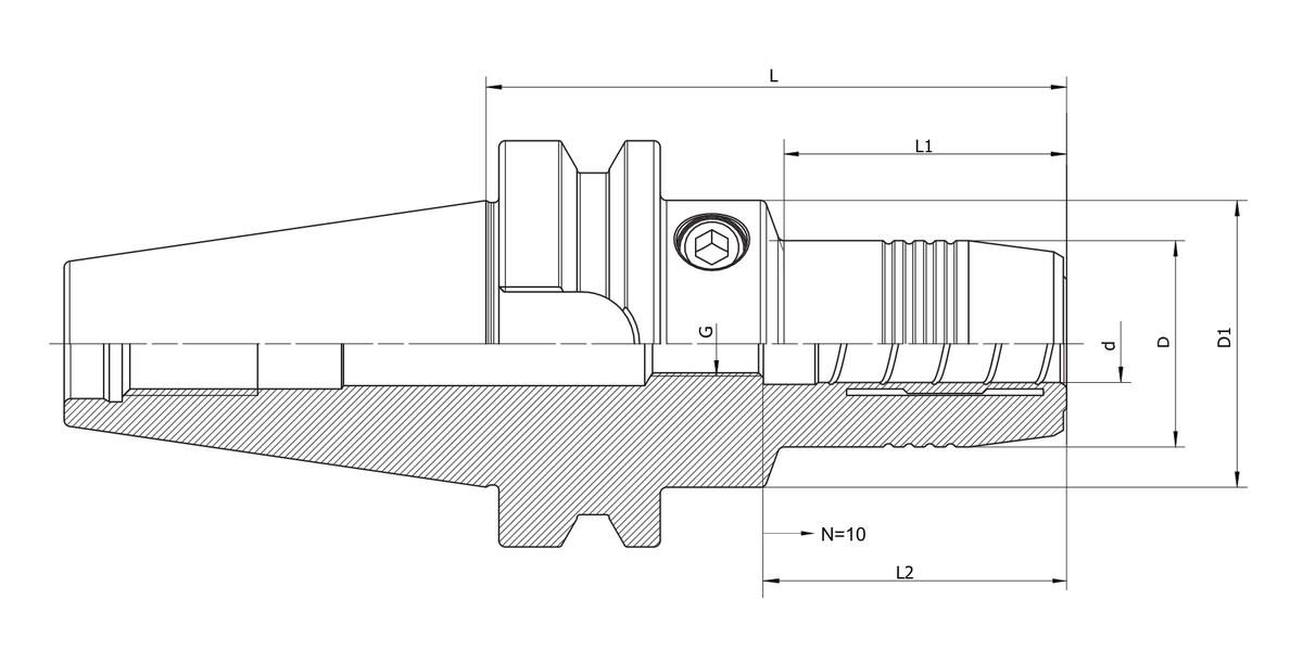
Dimension table
| Variant | d [mm] | D [mm] | D1 [mm] | L [mm] | L1 [mm] | L2 [mm] | G |
| BT40-HY06-90 | 6 | 28 | 50 | 90 | 43 | 38 | M5 |
| BT40-HY06-150 | 6 | 28 | 50 | 150 | 103 | 38 | M5 |
| BT40-HY06-200 | 6 | 28 | 50 | 200 | 153 | 38 | M5 |
| BT40-HY08-90 | 8 | 30 | 50 | 90 | 44 | 38 | M6 |
| BT40-HY08-150 | 8 | 30 | 50 | 150 | 104 | 38 | M6 |
| BT40-HY08-200 | 8 | 30 | 50 | 200 | 154 | 38 | M6 |
| BT40-HY10-90 | 10 | 32 | 50 | 90 | 44 | 42 | M8×1 |
| BT40-HY10-150 | 10 | 32 | 50 | 150 | 104 | 42 | M8×1 |
| BT40-HY10-200 | 10 | 32 | 50 | 200 | 154 | 42 | M8×1 |
| BT40-HY12-90 | 12 | 34 | 50 | 90 | 44 | 47 | M10×1 |
| BT40-HY12-150 | 12 | 34 | 50 | 150 | 104 | 47 | M10×1 |
| BT40-HY12-200 | 12 | 34 | 50 | 200 | 154 | 47 | M10×1 |
| BT40-HY14-90 | 14 | 36 | 50 | 90 | 44 | 47 | M10×1 |
| BT40-HY14-150 | 14 | 36 | 50 | 150 | 104 | 47 | M10×1 |
| BT40-HY14-200 | 14 | 36 | 50 | 200 | 154 | 47 | M10×1 |
| BT40-HY16-90 | 16 | 38 | 50 | 90 | 44 | 50 | M12×1 |
| BT40-HY16-150 | 16 | 38 | 50 | 150 | 104.5 | 50 | M12×1 |
| BT40-HY16-200 | 16 | 38 | 50 | 200 | 155 | 50 | M12×1 |
| BT40-HY18-90 | 18 | 40 | 50 | 90 | 45 | 50 | M12×1 |
| BT40-HY18-150 | 18 | 40 | 50 | 150 | 104.5 | 50 | M12×1 |
| BT40-HY18-200 | 18 | 40 | 50 | 200 | 155 | 50 | M12×1 |
| BT40-HY20-90 | 20 | 42 | 50 | 90 | 45 | 52 | M12×1 |
| BT40-HY20-150 | 20 | 42 | 50 | 150 | 105 | 52 | M16×1 |
| BT40-HY20-200 | 20 | 42 | 50 | 200 | 155 | 52 | M16×1 |
| BT40-HY25-100 | 25 | 57 | 62 | 100 | 55.5 | 58 | M16×1 |
| BT40-HY25-150 | 25 | 57 | 62 | 150 | 104 | 58 | M16×1 |
| BT40-HY25-200 | 25 | 57 | 57 | 200 | 173 | 58 | M16×1 |
| BT40-HY32-105 | 32 | 64 | 62 | 105 | 62 | 62 | M16×1 |
| BT40-HY32-150 | 32 | 64 | 62 | 150 | 106 | 62 | M16×1 |
| BT40-HY32-200 | 32 | 64 | 62 | 200 | 157 | 62 | M16×1 |
d – bore diameter (tool shank), D – diameter of the front clamping section, D1 – diameter of the body with the clamping screw, L – length from the flange face (spindle side) to the chuck front face, L1 – length of the front section with diameter D, L2 – bore depth from the chuck front face to the stop screw, G – thread of the stop screw for setting the tool projection (adjustment range 10 mm).
Read the complete designation of the selected variant. For example, BT40-HY12-90 means a BT40 taper, a hydraulic chuck (HY) for a Ø12 mm shank and length L = 90 mm.
How to select
- Check that the spindle has a BT40 interface (MAS 403 BT), not SK40.
- Diameter d = tool shank diameter (e.g. an end mill with a Ø12 shank = variant HY12). The shank must be cylindrical.
- Check the diameters D and D1 and the lengths L and L1 in the dimension table if the tool is to work close to walls or in a deep cavity.
- A hex key for the clamping screw is needed to clamp and release the tool.
FAQ
Will it fit my machine?
The holder has a BT40 taper to MAS 403 BT (JIS B 6339). Before purchasing, confirm that the standard, size and pull stud match the machine spindle requirements. BT40 and SK40 are different tapers, so the designation “40” alone is not sufficient to confirm the selection.
Which tools can be clamped?
Tools with a cylindrical shank whose diameter equals d of the selected variant: end mills, drills, reamers or chamfering tools. A smaller diameter can be clamped through a reduction sleeve in a chuck Ø12, Ø20 or Ø32. The bore depth L2 is given in the dimension table.
How do I clamp the tool?
Set the insertion depth with the stop screw, insert the shank into the bore and tighten the clamping screw with a hex key to the stop. To release the tool, loosen the clamping screw.
How does it differ from a shrink fit chuck?
A hydraulic chuck does not need a shrink fit unit: the tool is clamped and released with a hex key, so a tool change is quick. The oil in the chuck also dampens vibration.
How does it differ from an ER collet chuck?
A hydraulic chuck clamps the shank without a collet and nut, evenly around its full circumference, with runout ≤ 0.003 mm and vibration damping. An ER collet chuck covers different diameters by changing the collet.
BBT40 – BT40 with flange face contact (BIG-PLUS)
Variants whose code starts with BBT40- have a BBT40 taper. This is a BT40 taper to JIS B 6339 (MAS 403) with a flange face that contacts the spindle face in a BIG-PLUS spindle. The holder is then seated on the taper and on the flange face at the same time (taper and face contact). This gives a stiffer and more stable seating, especially at high spindle speeds, a repeatable position after every automatic tool change, higher machining accuracy and a better surface finish.
In a standard BT40 spindle (without BIG-PLUS) a BBT40 holder works like a standard BT40 holder: it is seated on the taper only. For such a spindle the lower-priced variant with the code BT40- in the same size is sufficient, if it is on the list.
Before purchasing, check in the machine documentation whether the spindle has the BIG-PLUS system (BBT40). The pull stud is selected in the same way as for BT40 (M16 thread), according to the spindle requirements.
A tool is clamped in a BBT40 chuck in the same way as in BT40: with a hex key for the clamping screw, no shrink fit unit needed.
| Taper | BBT40: BT40 with flange face contact (JIS B 6339), for BIG-PLUS spindles; works like BT40 in a standard BT40 spindle |
| Tool clamping | hydraulic: clamping screw and expansion sleeve with oil chamber |
| Tool shank diameter d | 6, 8, 10, 12, 14, 16, 18, 20, 25 or 32 mm (depending on variant) |
| Tool shank | cylindrical, diameter equal to d of the variant |
| Smaller shank diameters | with reduction sleeves for chucks Ø12, Ø20 and Ø32 (sleeves not included) |
| Length L | 90 mm (Ø25: 100 mm; Ø32: 105 mm) |
| Holder runout | ≤ 0.003 mm |
| Balance grade | at least G6.3 (many pieces are balanced to G2.5 at 25,000 rpm: ask us and we will check the label of the specific piece) |
| Coolant | AD version (central coolant supply) |
| Tool projection setting | stop screw with thread G in the bore (dimension table), adjustment range 10 mm |
| Tool clamping and release | hex key for the clamping screw |
| Pull stud thread | M16 (as BT40) |
| Standard | JIS B 6339 (BBT taper) |
BBT40 balance grade: at least G6.3. Many BBT40 holders of this type are balanced to G2.5 at 25,000 rpm (more precise). If you need G2.5 for high spindle speeds, write to us before purchasing — we will check the label of the specific piece before shipping.
BBT40 – dimension table
| Variant | d [mm] | D [mm] | D1 [mm] | L [mm] | L1 [mm] | L2 [mm] | G |
| BBT40-HY06-90 | 6 | 28 | 50 | 90 | 43 | 38 | M5 |
| BBT40-HY08-90 | 8 | 30 | 50 | 90 | 44 | 38 | M6 |
| BBT40-HY10-90 | 10 | 32 | 50 | 90 | 44 | 42 | M8×1 |
| BBT40-HY12-90 | 12 | 34 | 50 | 90 | 44 | 47 | M10×1 |
| BBT40-HY14-90 | 14 | 36 | 50 | 90 | 44 | 47 | M10×1 |
| BBT40-HY16-90 | 16 | 38 | 50 | 90 | 44 | 50 | M12×1 |
| BBT40-HY18-90 | 18 | 40 | 50 | 90 | 45 | 50 | M12×1 |
| BBT40-HY20-90 | 20 | 42 | 50 | 90 | 45 | 52 | M12×1 |
| BBT40-HY25-100 | 25 | 57 | 57 | 100 | 73 | 58 | M16×1 |
| BBT40-HY32-105 | 32 | 64 | 62 | 105 | 62 | 62 | M16×1 |
d – bore diameter (tool shank), D – diameter of the front clamping section, D1 – diameter of the body with the clamping screw, L – length from the flange face (spindle side) to the chuck front face, L1 – length of the front section with diameter D, L2 – bore depth from the chuck front face to the stop screw, G – thread of the stop screw for setting the tool projection (adjustment range 10 mm).
Check the full designation of the selected variant. Example: BBT40-HY12-90 is a BBT40 taper, a hydraulic chuck (HY) for a Ø12 mm shank and length L = 90 mm.
BBT40 – questions
What is the difference between BBT40 and BT40?
BBT40 has the same taper as BT40, but in a BIG-PLUS spindle it also contacts the spindle with the flange face. This taper and face contact makes the seating of the holder stiffer. A standard BT40 holder is seated on the taper only.
Does BBT40 fit a standard BT40 spindle?
Yes. In a standard BT40 spindle a BBT40 holder works like a standard BT40 holder (contact on the taper only). The benefit of the face contact is available only in a BIG-PLUS spindle.
How do I tell a BBT40 variant from a BT40 variant?
By the code: BBT40 variants start with BBT40- (e.g. BBT40-HY12-90), standard BT40 variants with BT40- (e.g. BT40-HY12-90).
Select a pull stud
For a BT holder compare BT pull studs in the appropriate size.
Confirm the selection against the spindle requirements: head profile and angle, thread, length, bore and seal.
Bestsellers
-
Bestseller
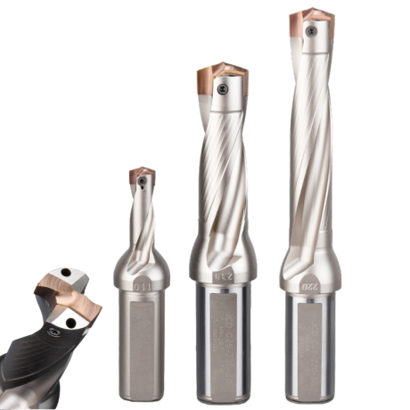
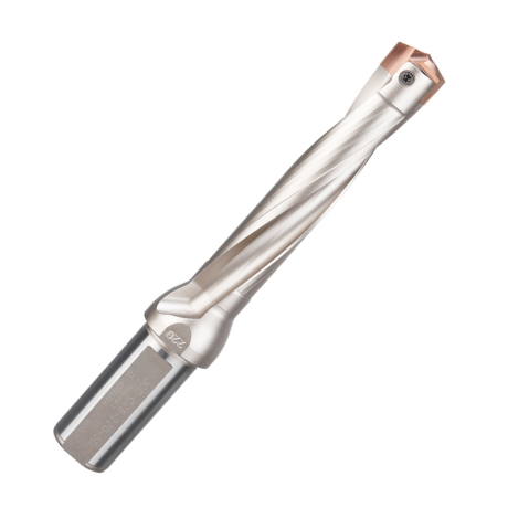
JCD modular drill with replaceable tip - internal cooling, for deep holes | GrotXD
JCD C20-100-3D Ø10~10.9 JCD C20-110-3D Ø11~11.9 JCD C20-120-3D Ø12~12.9 JCD C20-130-3D Ø13~13.9 JCD C20-140-3D Ø14~14.9 + 61 morePrice €69.52Price €56.52without VAT -
Price €17.09Price €13.90without VAT
-
Price €7.07Price €5.74without VAT
-
Price €7.52Price €6.12without VAT
-
Bestseller
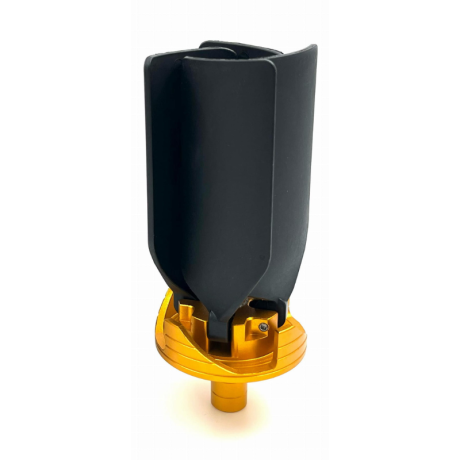
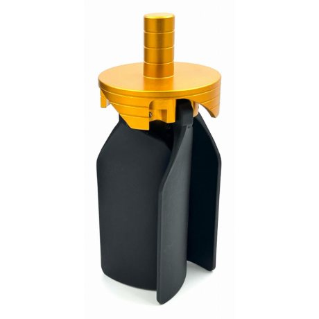 Other Accessories 0.00
CNC Chip Fan / Chip Blower
Complete CNC chip fan Kit: blades, springs, pins and screwsPrice €53.56Price €43.55without VAT -
Bestseller
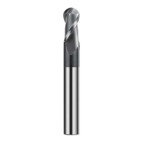
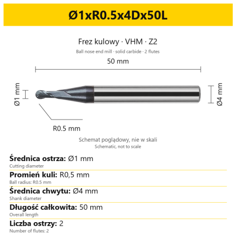 Ball Nose End Mills 0.00
2-Flute Carbide Ball Nose End Mill - HYPERCUT
Ø1xR0.5x4Dx50L Ø1.5xR0.75x4Dx50L Ø2xR1x4Dx50L Ø2.5xR1.25x4Dx50L Ø3xR1.5x3Dx50L + 26 morePrice €10.09Price €8.21without VAT -
Bestseller
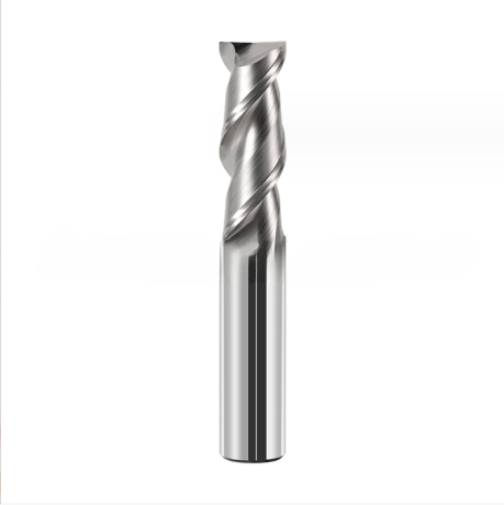
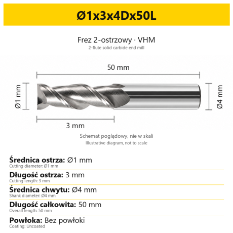 2-Flute End Mills 0.00
2-Flute Carbide End Mill for Aluminium
Ø1x3x4Dx50L Ø1.5x4x4Dx50L Ø2x6x4Dx50L Ø2.5x7.5x4Dx50L Ø3x9x3Dx50L + 31 morePrice €5.33Price €4.33without VAT -
Bestseller
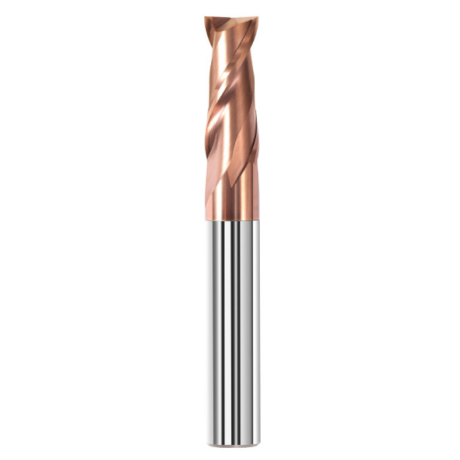
 2-Flute End Mills 0.00
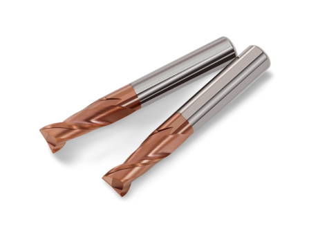
2-Flute Carbide End Mill for Steel 55 HRC - TiSiN - Solid Carbide
Ø6x24x6Dx75L Ø8x25x8Dx75L Ø4x20x4Dx100L Ø5x30x5Dx100L Ø6x30x6Dx100L + 31 morePrice €4.38Price €3.56without VAT -
Bestseller
 Ball Nose End Mills 0.00
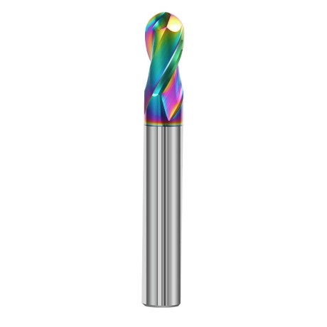
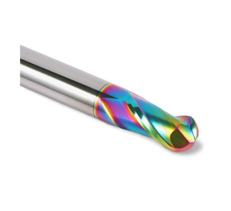
2-Flute DLC Coated Carbide Ball Nose End Mill| DuraEdge Alu
Ø1.0xR0.5x4Dx50L Ø1.5xR0.75x4Dx50L Ø2.0xR1x4Dx50L Ø2.5xR1.25x4Dx50L Ø3.0xR1.5x3Dx50L + 34 morePrice €7.85Price €6.38without VAT -
Bestseller
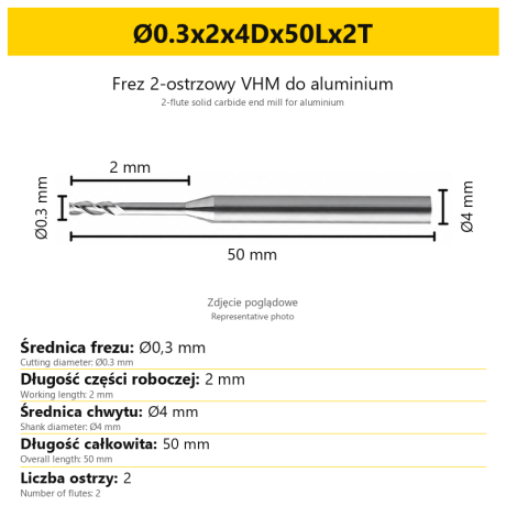 2-Flute End Mills 0.00
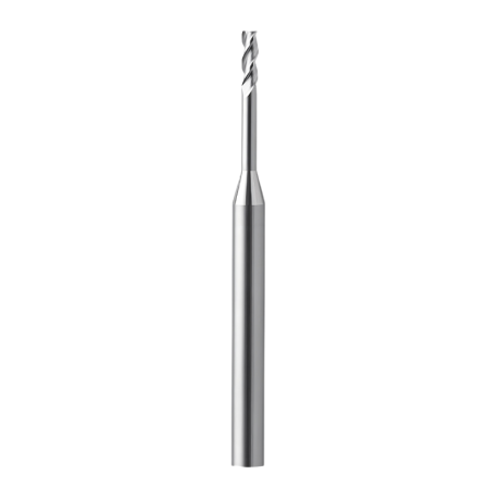
2-Flute End Mill for Aluminium | VHM | Miniature Ø0.3 - Ø0.9
Ø0.3x2x4Dx50Lx2T Ø0.3x3x4Dx50Lx2T Ø0.3x4x4Dx50Lx2T Ø0.4x2x4Dx50Lx2T Ø0.4x3x4Dx50Lx2T + 28 morePrice €7.95Price €6.47without VAT -
Bestseller
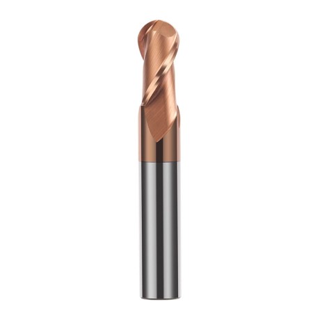
 Ball Nose End Mills 0.00
2-Flute TiSiN Coated Carbide Ball Nose End Mill
Ø1xR0.5x4Dx50L Ø1.5xR0.75x4Dx50L Ø2xR1x4Dx50L Ø2.5xR1.25x4Dx50L Ø3xR1.5x3Dx50L + 38 morePrice €7.24Price €5.89without VAT -
Bestseller
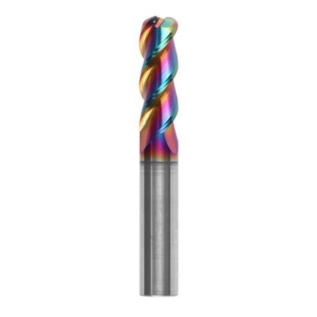
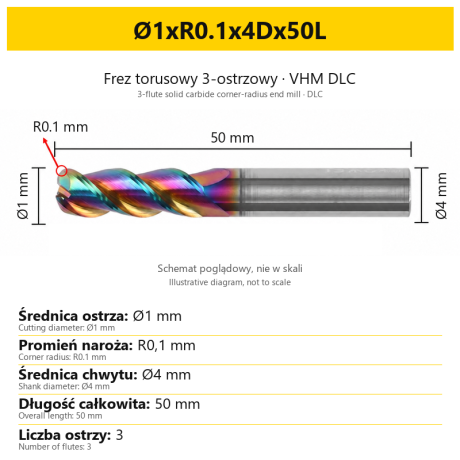
3-Flute Carbide Corner Radius End Mill for Aluminium| AL DLC
Ø1xR0.1x4Dx50L Ø1xR0.2x4Dx50L Ø1xR0.3x4Dx50L Ø1.5xR0.1x4Dx50L Ø1.5xR0.2x4Dx50L + 137 morePrice €5.89Price €4.79without VAT -
Bestseller
 3-Flute End Mills 0.00
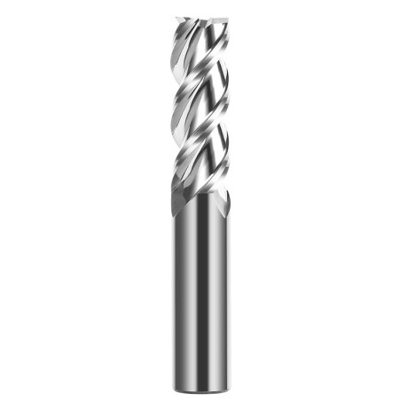
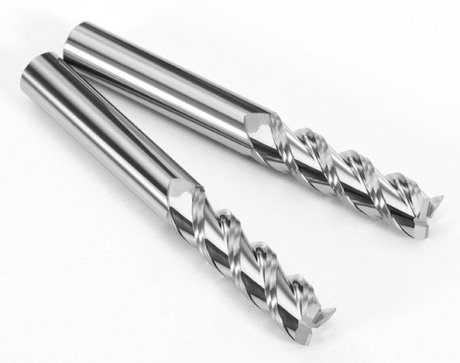
3-Flute Carbide End Mill VHM Z-3 for Aluminium| TriMill AL
Ø1x3xD4x50L Ø1.5x5x4Dx50L Ø2x6x4Dx50L Ø2.5x8x4Dx50L Ø3x9x3Dx50L + 41 morePrice €5.08Price €4.13without VAT -
Bestseller
 Countersinks 0.00
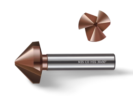
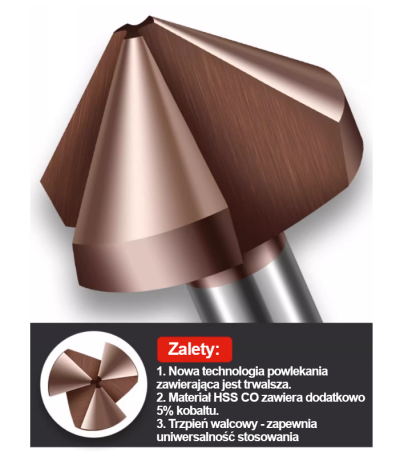
3-Flute Countersink Fi4.5-fi60, 90° - HSS-CO - 5% Kobaltu | Straight Shank
Ø4.5 x 4 x 90° x 40L Ø5 x 5 x 90° x 45L Ø6.3 x 5 x 90° x 45L Ø8.3 x 6 x 90° x 50L Ø10.4 x 6 x 90° x 50L + 12 morePrice €4.79Price €3.89without VAT -
Bestseller
 3-Flute End Mills 0.00
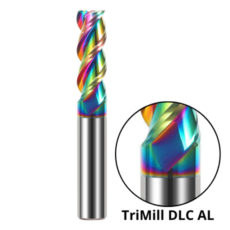
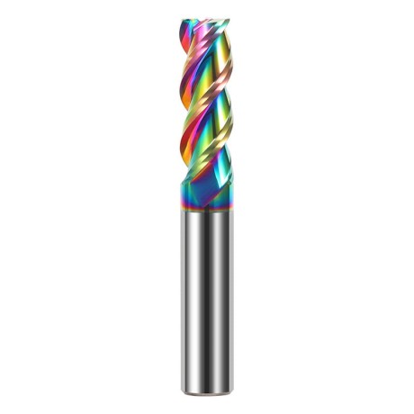
3-Flute DLC Coated Carbide End Mill | TriMill DLC AL
Ø1x3x4Dx50L Ø1.5x5x4Dx50L Ø2x6x4Dx50L Ø2.5x8x4Dx50L Ø3x8x3Dx50L + 38 morePrice €5.05Price €4.10without VAT -
Bestseller

 3-Flute End Mills 0.00
3-Flute HRC65 DLC Coated Carbide End Mill, U-Shaped Flute, for Aluminium | DuraEdge3 Alu
Ø1x3x4Dx50L Ø1.5x5x4Dx50L Ø2x6x4Dx50L Ø2.5x8x4Dx50L Ø3x9x3Dx50L + 40 morePrice €6.73Price €5.47without VAT