


2-Flute TiSiN Coated Carbide Ball Nose End Mill
Shipping costs are not included in the price.
Shipping costs are not included in the price.
Ask about the product

The administrator of personal data is Kortools. We process it to respond to your inquiry. More information regarding the processing of personal data can be found in privacy policy.
Select a product variant:
Individual variants may differ in price
Product code: 4405-36841
Product description
TiSiN solid carbide ball nose end mill · 2 flutes
For 3D contour and surface milling on CNC machines
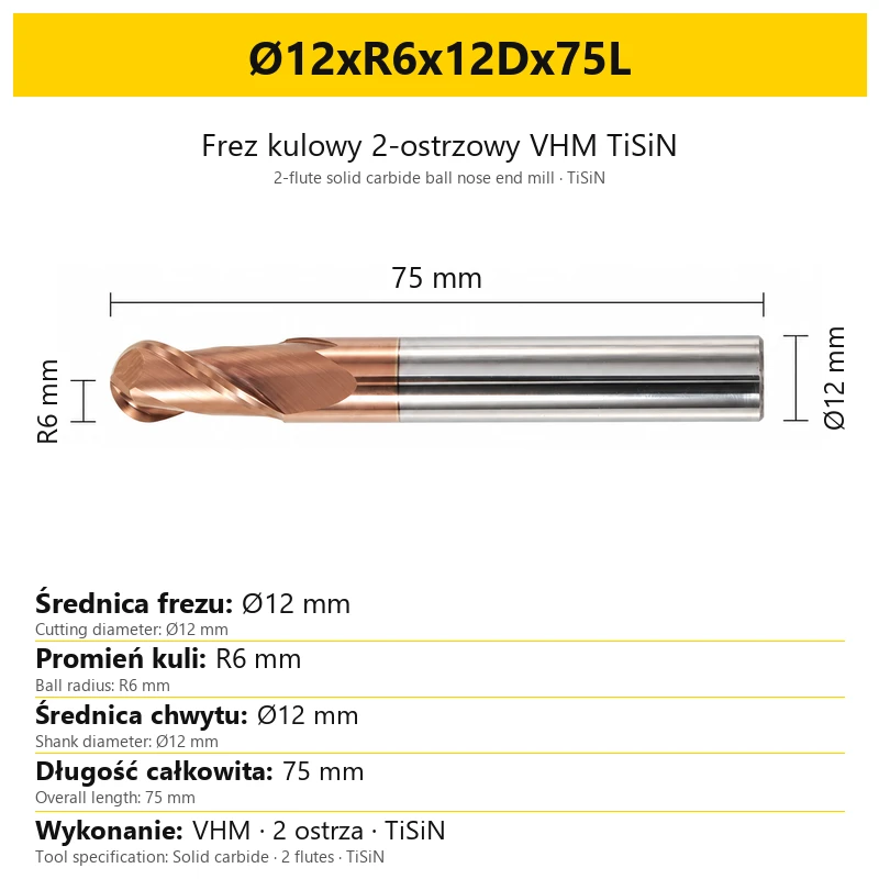
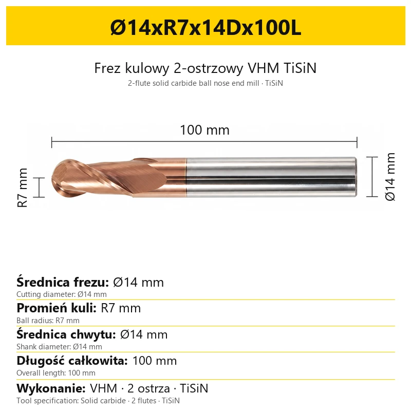
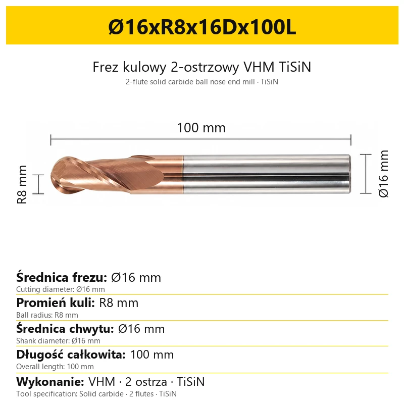
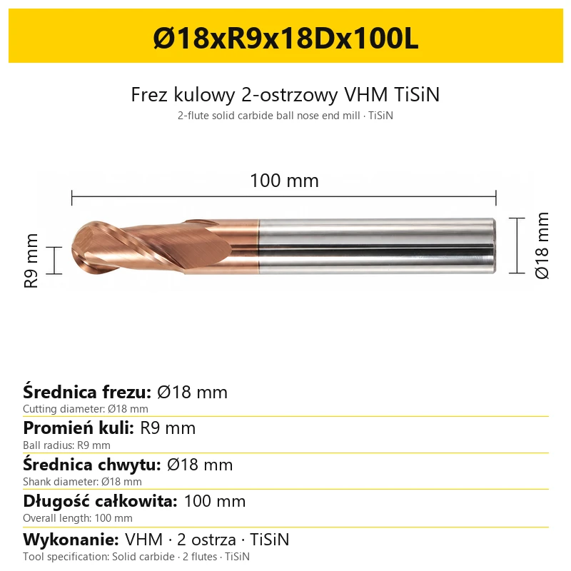
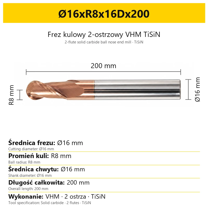
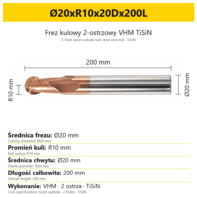
A solid carbide ball nose end mill with two flutes and a TiSiN coating, designed for 3D contour and surface milling on CNC machines. The rounded cutting tip has a spherical radius R.
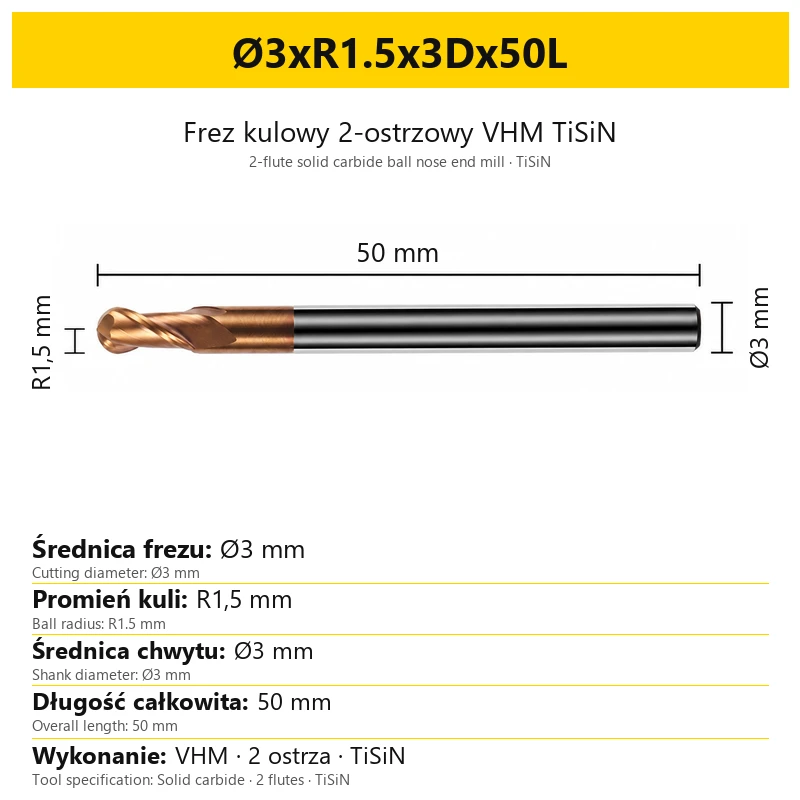
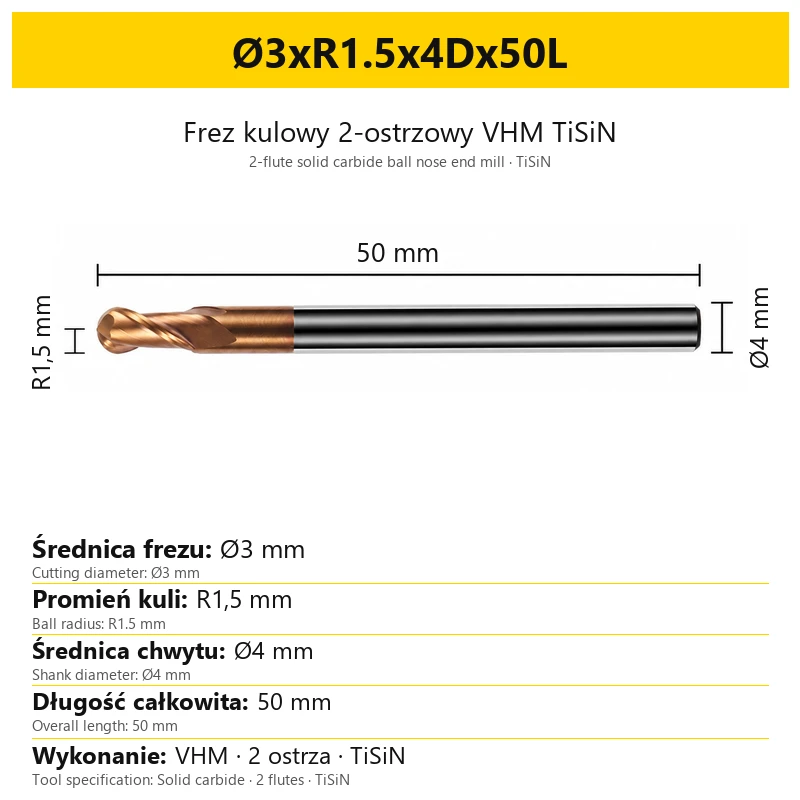
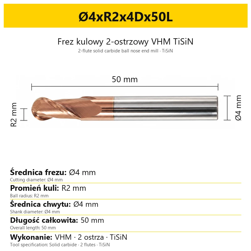
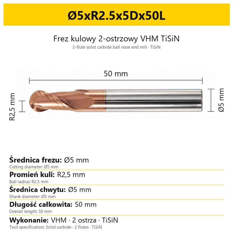
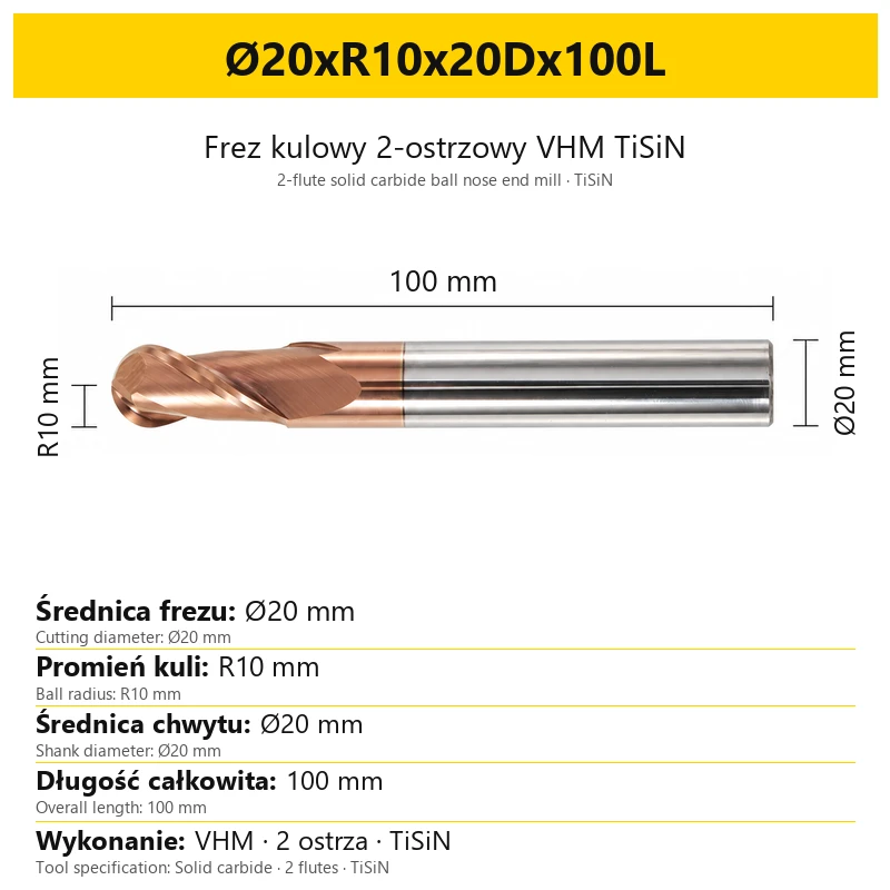
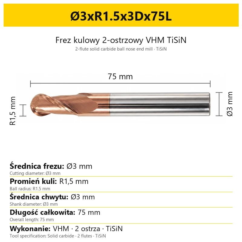
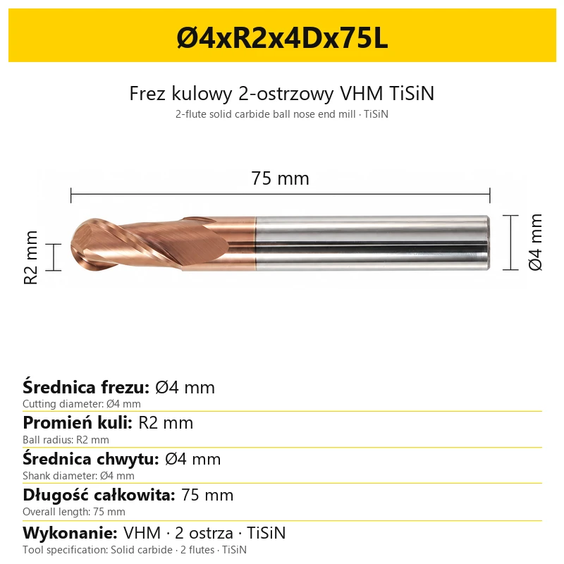
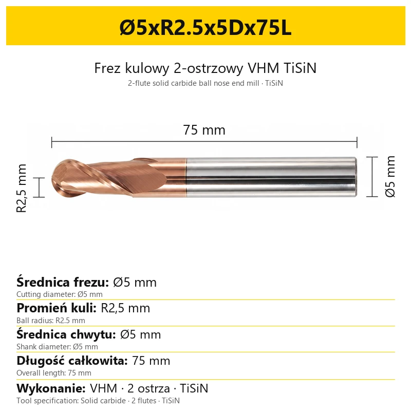
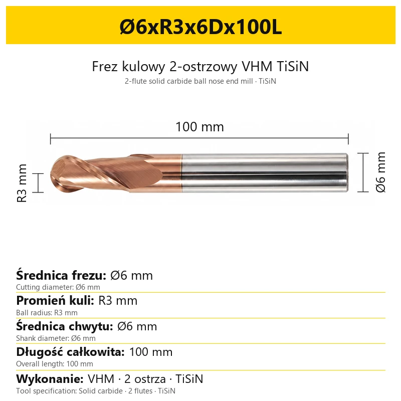
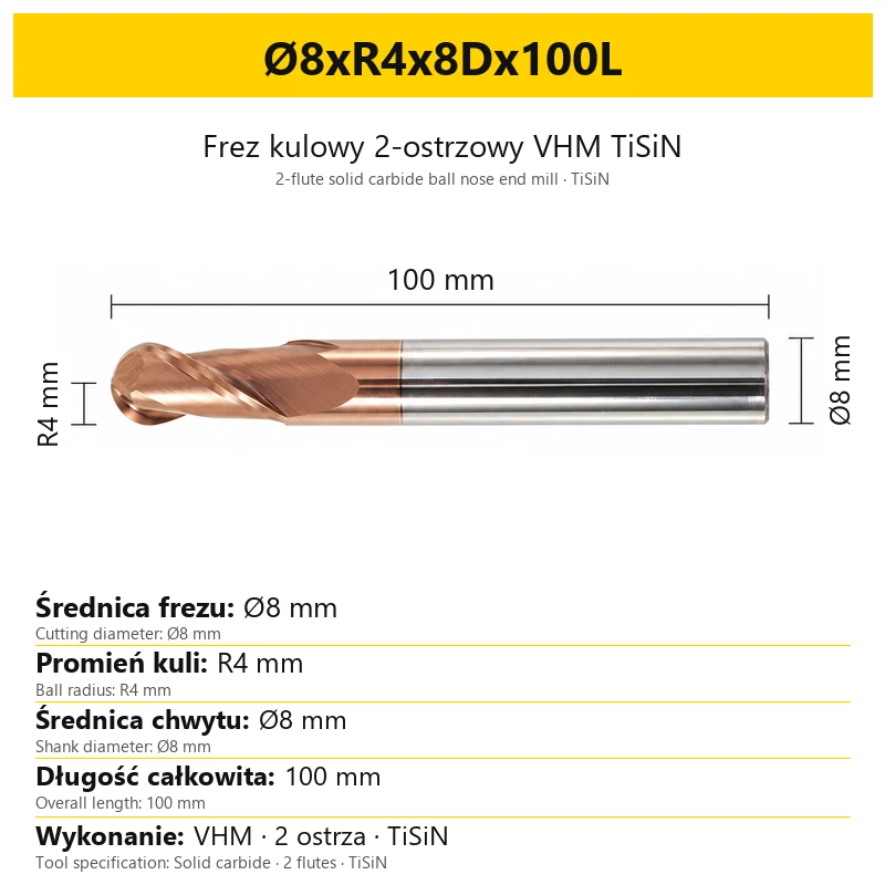
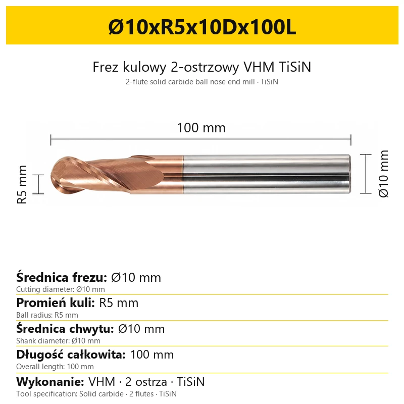
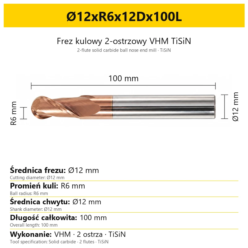
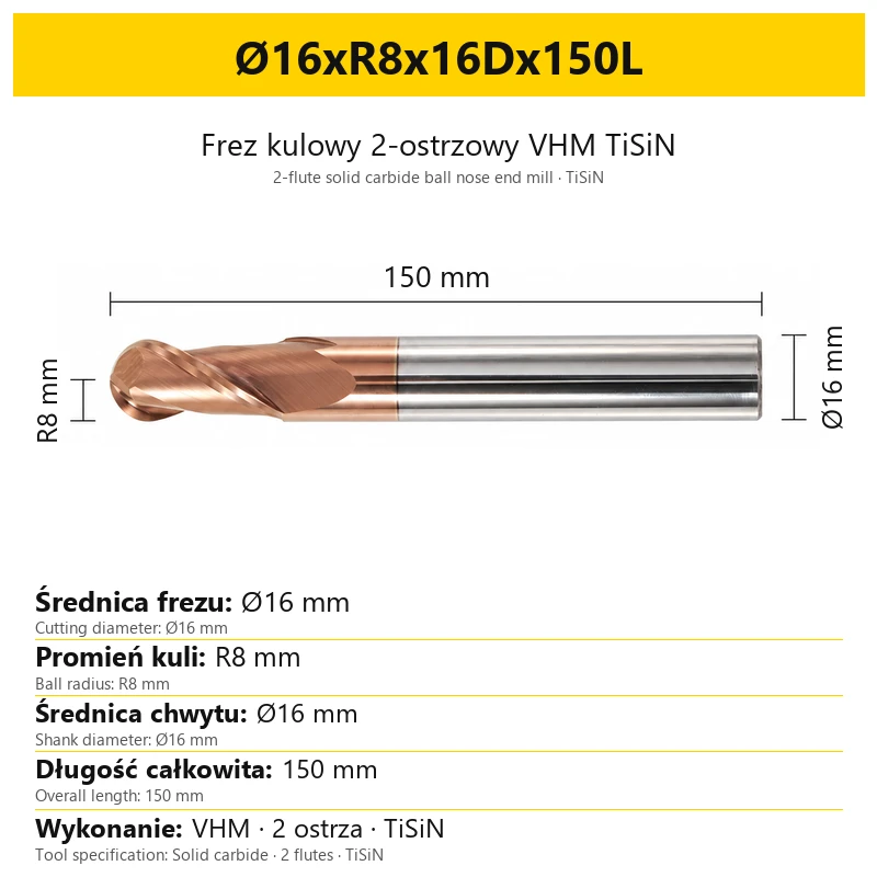
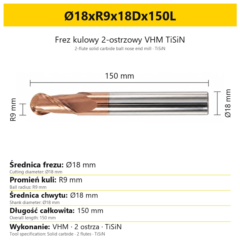
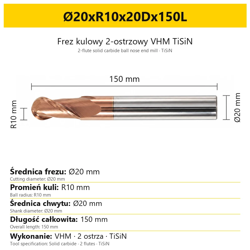
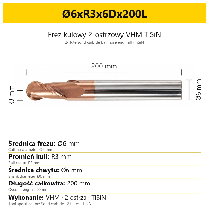
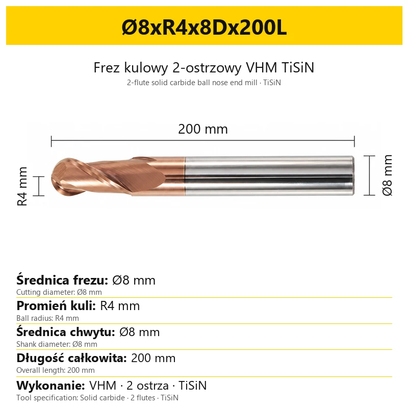
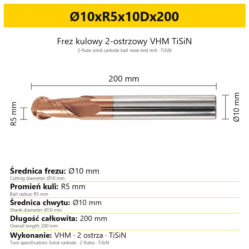
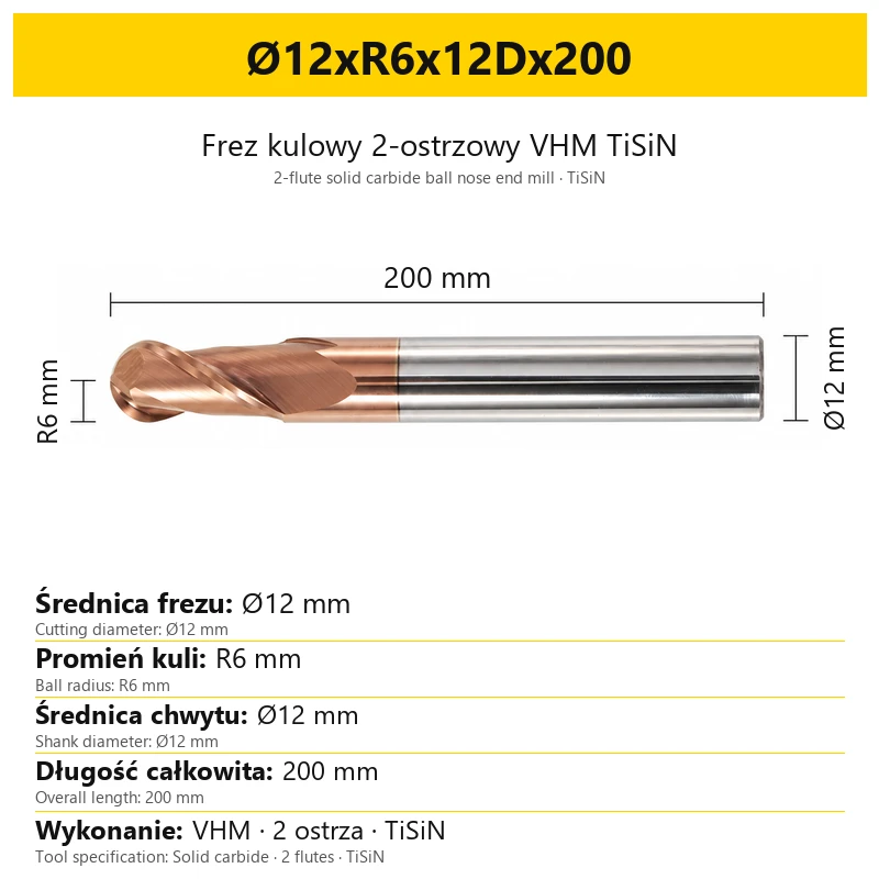
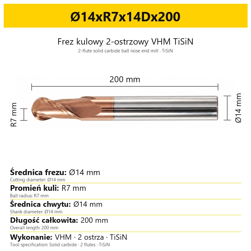
Select the variant by its cutting diameter, ball radius, shank diameter and overall length. These are separate dimensions: tools with the same cutting diameter may have different shanks or lengths. The variant designation and its dimension card show the exact combination.
1. Ball nose milling applications
| Operation | Role of the ball nose geometry |
|---|---|
| 3D surface milling | Machining freeform surfaces with successive toolpaths. The ball radius is one of the dimensions to enter when defining the tool geometry in CAM. |
| Contour milling | Machining curved surfaces and rounded features. Select the ball size for the workpiece geometry and access to the machining area. |
| CNC milling | Machining with a programmed toolpath. Enter the dimensions of the exact tool variant that will be mounted in the spindle. |
The designation R identifies the radius of the spherical tip. It is not a small corner radius on a flat end mill. Before running the program, check that a ball nose tool has been selected in the CAM library and that its diameter and radius match the actual tool.
2. Construction and specifications
| Parameter | Value or meaning |
|---|---|
| Tool type | Solid ball nose end mill |
| Tool material | VHM — solid carbide |
| Coating | TiSiN — titanium silicon nitride |
| Number of flutes | 2 — designated 2T |
| Tip geometry | Spherical, with radius R |
| Cutting diameter | 1–20 mm, depending on the variant |
| Ball radius | R0.5–10 mm, depending on the variant |
| Shank diameter | 3–20 mm, depending on the variant |
| Overall length | 50, 60, 75, 100, 150 or 200 mm, depending on the variant |
| Shank type | Cylindrical |
The ranges describe the tool family. Not every cutting diameter is available with every overall length or shank diameter. Check the product selector for available combinations. The diameter of the ball section is twice its radius: Ø = 2 × R.
3. Workpiece materials
The application range includes the material groups below. Cutting conditions must account for the specific grade, material condition and operation; a material group alone does not determine spindle speed or feed rate.
| Material group | Examples and scope |
|---|---|
| Steels | Steel and hardened steel. Account for the actual workpiece hardness when selecting the tool and cutting conditions. |
| Stainless steels | Stainless steel machining with conditions selected for the particular grade and milling operation. |
| Superalloys and heat-resistant materials | Select for the specific alloy and setup; do not apply one set of cutting conditions to every material in this group. |
| Non-ferrous metals | Aluminium, copper and brass. |
| Plastics and non-metallic materials | PLEXI, PVC, POM, PE and plywood. Match the machining conditions to the specific material and required workpiece geometry. |
4. Understanding the variant dimensions
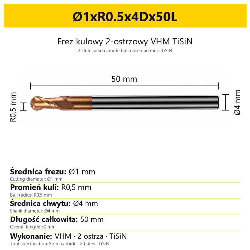
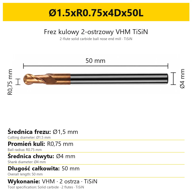
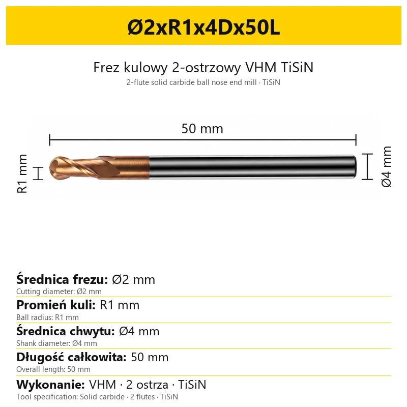
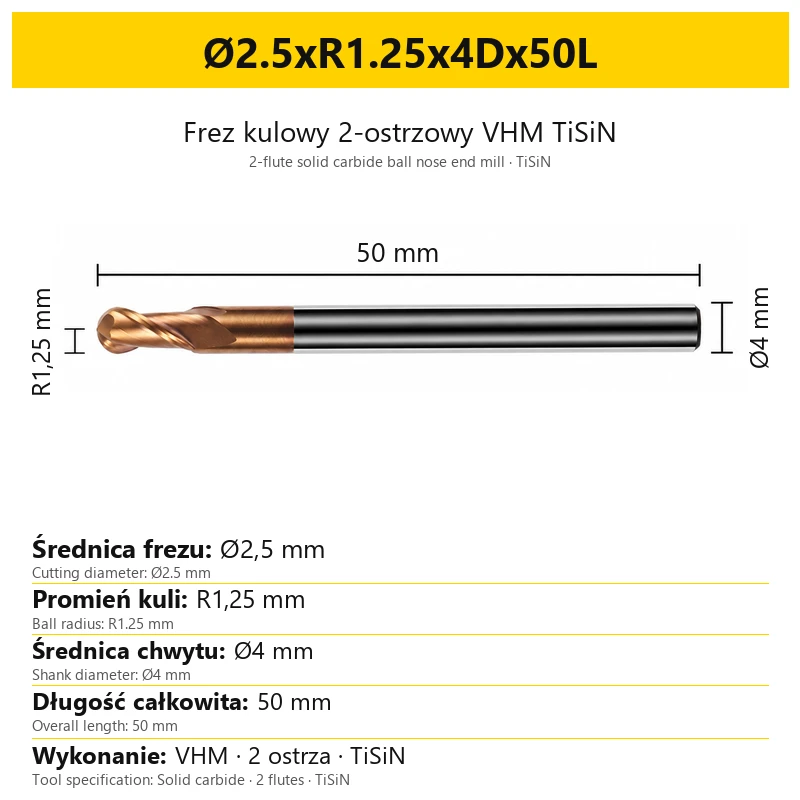
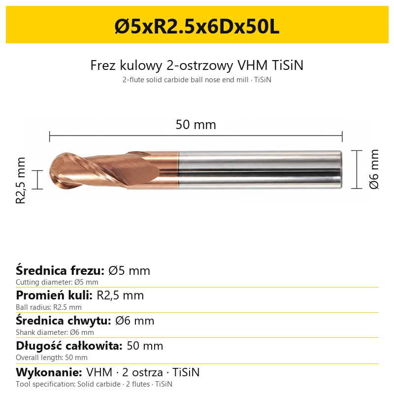
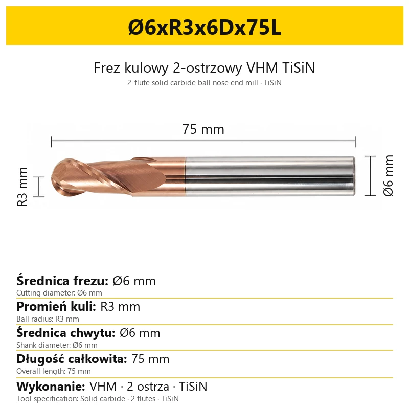
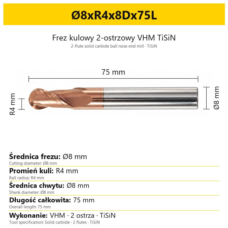
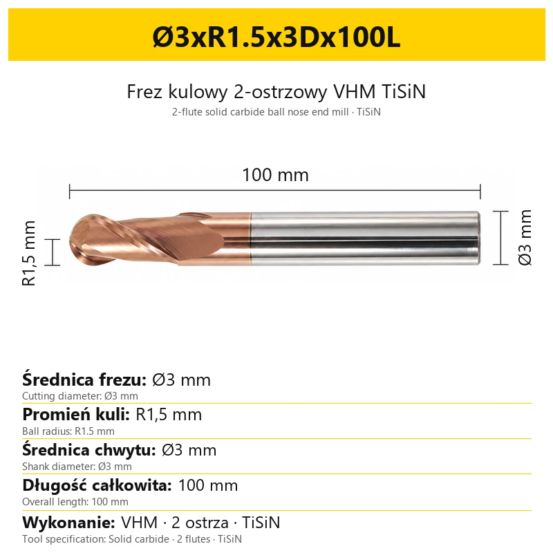
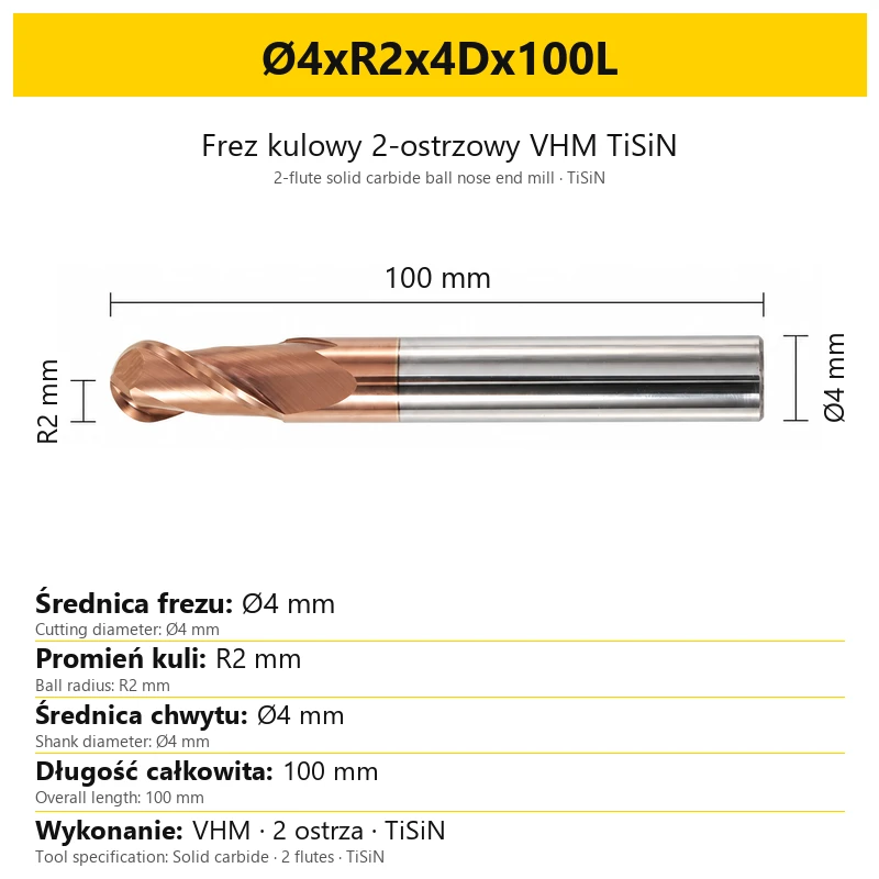
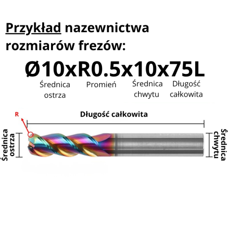
Example designation: Ø5xR2.5x6Dx50L. It describes a 5 mm cutting diameter, a 2.5 mm ball radius, a 6 mm shank and a 50 mm overall length. All dimensions are in millimetres.
| Element | Meaning | Value in the example |
|---|---|---|
| Ø5 | Cutting diameter | 5 mm |
| R2.5 | Radius of the spherical tip | 2.5 mm |
| 6D | Shank diameter | 6 mm |
| 50L | Overall tool length | 50 mm |
Variant designations may use a decimal point while the Polish dimension cards use a comma: R2.5 and R2,5 identify the same radius. In these designations, the letter D after a number refers to the shank diameter.
5. Selecting diameter, radius and length
- Check radius R. Compare the spherical tip with the workpiece geometry and the tool definition in CAM. Do not confuse the radius with the cutting diameter.
- Select the cutting diameter. Account for access to the machining area and clearance for the tool and shank. Check the full designation of the chosen variant.
- Check the shank diameter. Match the holder to the value followed by D. This dimension may differ from the cutting diameter.
- Select the overall length. Choose a tool that provides the required access. Once mounted, limit stick-out to the reach needed for the operation.
- Compare the dimension card and selector. Check all four dimensions before ordering. The selected variant shows its current price and availability.
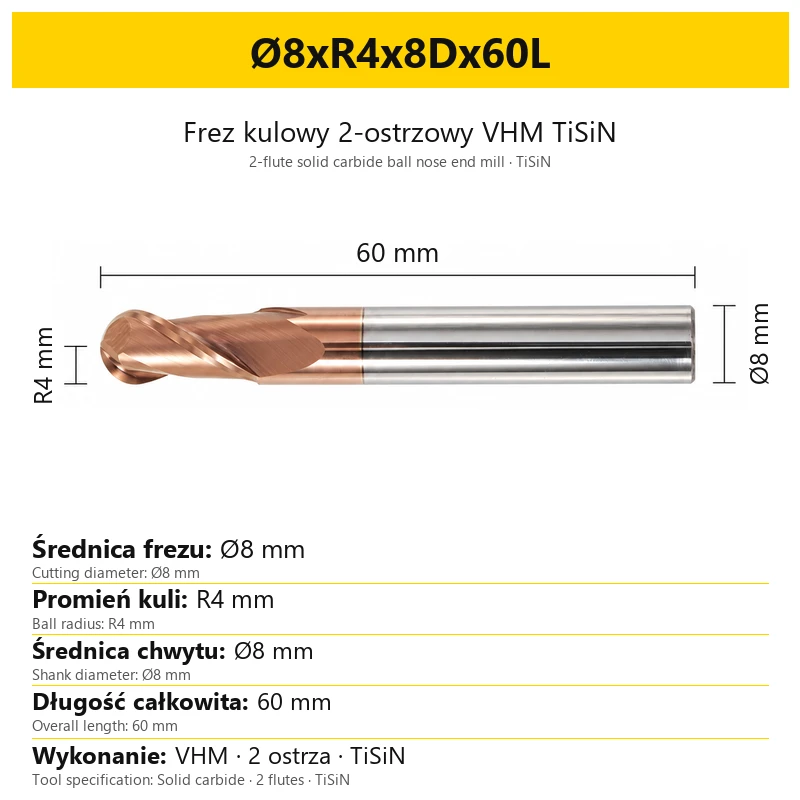
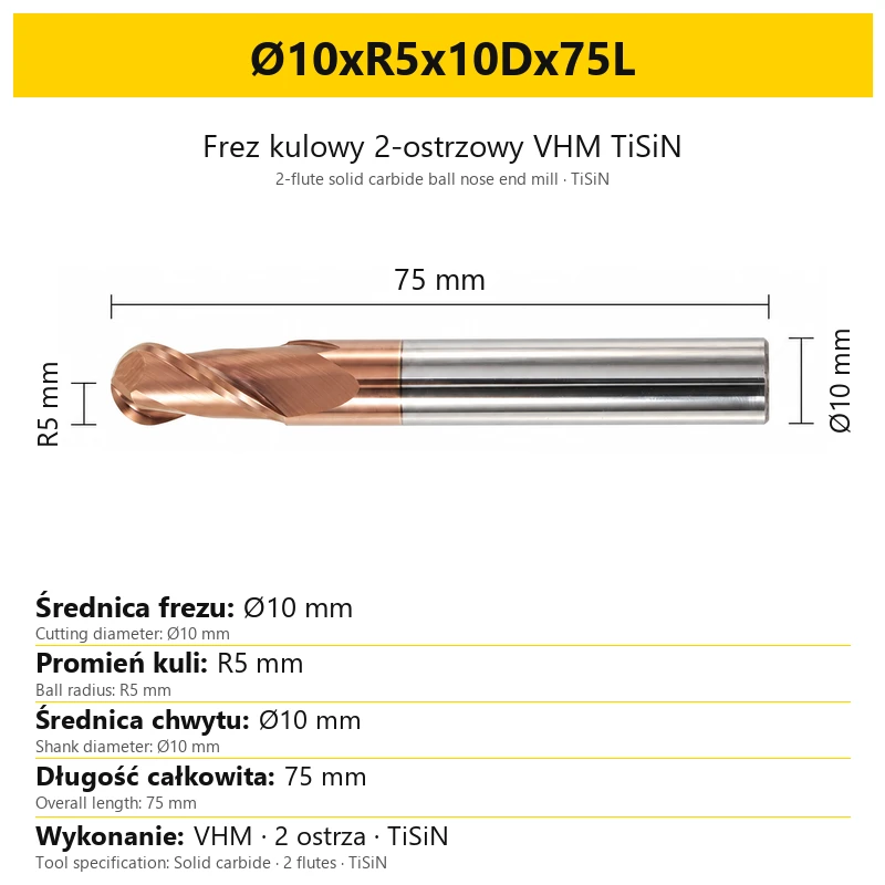
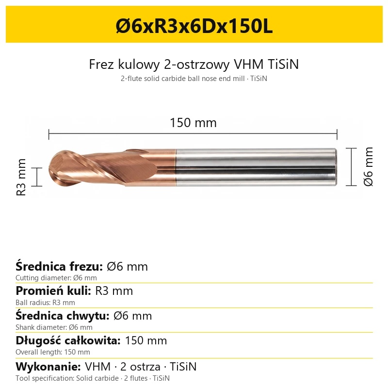
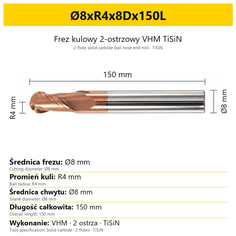
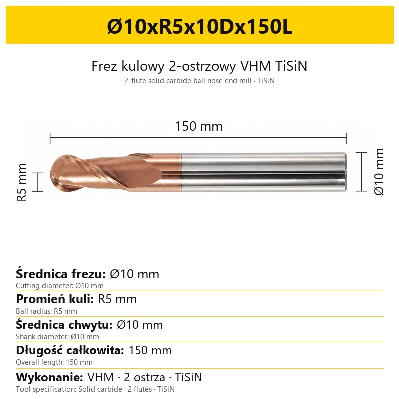
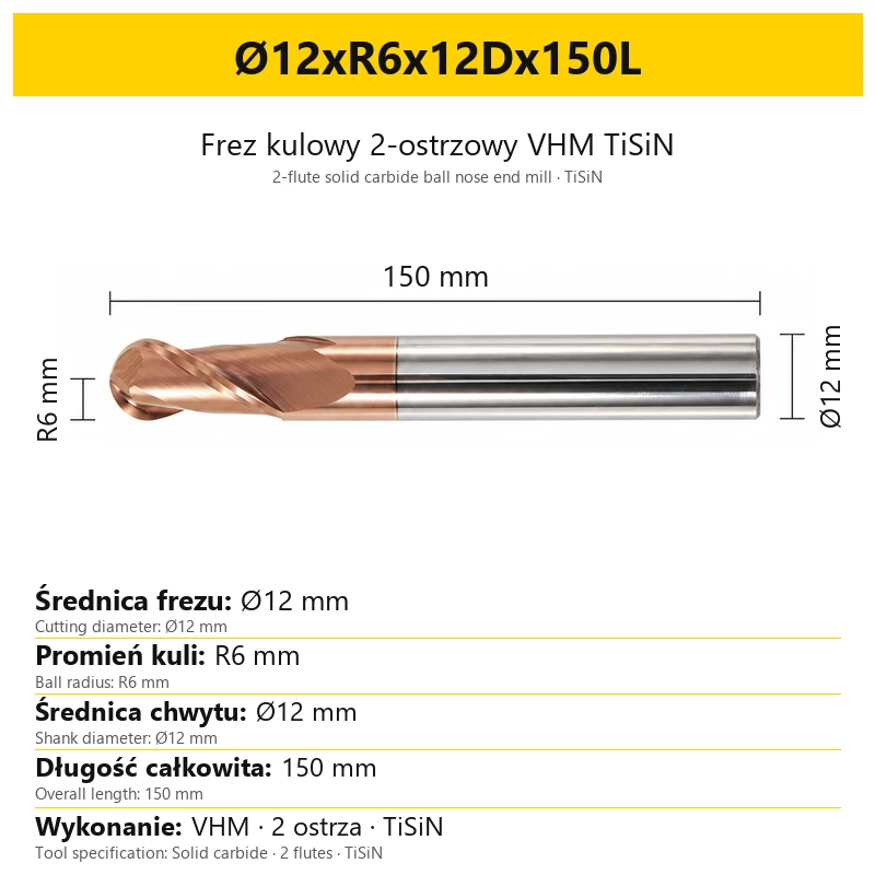
The photographs on the dimension cards are illustrative. Select dimensions from the labels and variant designation; the photograph is not a scale drawing. This also applies to tools with the same cutting diameter and different overall lengths.
6. Tool holding and machining setup
The tool is intended for CNC machines with a suitable spindle and tool holder. Before machining, check tool seating and runout. Do not transfer cutting settings automatically between variants with different diameters and lengths.
- Check clamping and runout. Correct any seating problem before cutting. Inspect the cutting section and make sure the shank is properly clamped.
- Minimise stick-out. Extend the tool only as far as the operation requires, while maintaining correct shank engagement in the holder.
- Account for a long stick-out in the settings. If longer reach is necessary, adjust spindle speed, feed and tool load accordingly. A longer tool does not imply that the settings for a short tool can be used unchanged.
- Respond to vibration. If vibration or irregular cutting occurs, check tool holding and cutting conditions before continuing.
A handheld drill or low-speed bench drill does not replace a CNC milling machine for this operation. Selecting spindle speed, feed and stock allowance requires information about the workpiece material, cutting diameter, toolpath and actual stick-out.
7. What the order includes
| Item | Order specification |
|---|---|
| Sales unit | 1 TiSiN-coated solid carbide ball nose end mill with two flutes |
| Size | The variant selected on the product page |
The quantity field specifies the number of individual tools in the chosen size. Different dimensions shown in the gallery illustrate available tool versions; they do not mean that all sizes are supplied as one set.
8. Frequently asked questions
What does R3 mean?
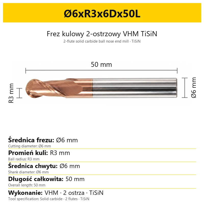
R3 identifies a spherical tip with a 3 mm radius. The corresponding ball section is 6 mm in diameter. Read the shank diameter and overall length separately from the variant designation.
Does a 5 mm cutter always have a 5 mm shank?
No. This family also includes tools with a cutting diameter smaller than the shank. Select the holder using the dimension marked D rather than the cutting diameter alone.
Does 200L mean a 200 mm length of cut?
No. 200L specifies the overall tool length. It does not define the cutting length or the permissible depth of a single pass.
Can I determine the size from the photograph?
The photograph is illustrative. The labelled dimensions and variant designation define the size. Before ordering, compare the cutting diameter, radius R, shank diameter and overall length.
Related products
-
E006-379B3


Carbide Corner Rounding End Mill
-
A31B-1652FBestseller


Carbide T-Slot End Mill - TiSiN Coated
-
0678-65504Bestseller


Carbide Corner Rounding End Mill - TiSiN Coated
-
1670-1921ABestseller


4-Flute TiSiN Coated Carbide Corner Radius End Mill, up to 55HRC
-
F677-248B8Bestseller
 3-Flute End Mills 0.00
3-Flute Carbide End Mill VHM Z-3 for Aluminium| TriMill AL
-
A31B-1652F_2Bestseller

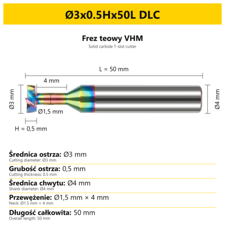
4-Flute Carbide T-Slot End Mill DLC


Bestsellers
-
Bestseller
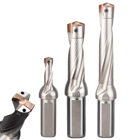
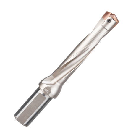
JCD modular drill with replaceable tip - internal cooling, for deep holes | GrotXD
JCD C20-100-3D Ø10~10.9 JCD C20-110-3D Ø11~11.9 JCD C20-120-3D Ø12~12.9 JCD C20-130-3D Ø13~13.9 JCD C20-140-3D Ø14~14.9 + 61 morePrice €69.86Price €56.79without VAT -
Bestseller
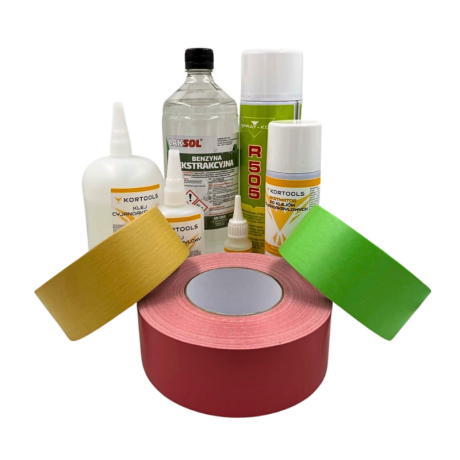
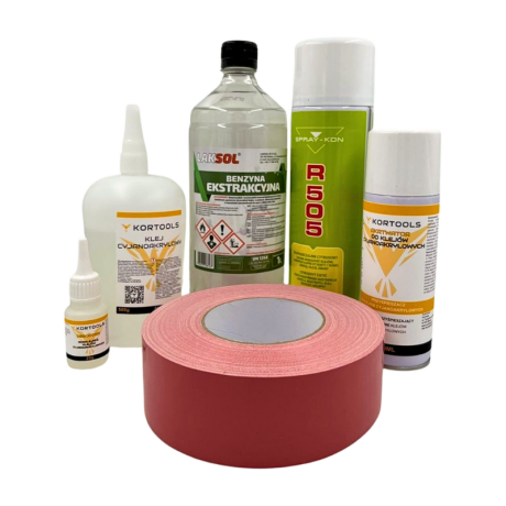
Kortools Adhesive + Tape CNC Workholding Kit
Yellow tape 5cm x 50m; adhesive 100g Yellow tape 5cm x 50m; adhesive 500g Yellow tape 10cm x 50m; adhesive 100g Yellow tape 10cm x 50m; adhesive 500g Green tape 5cm x 50m; adhesive 100g + 7 morePrice €44.66Price €36.31without VAT -
Price €17.18Price €13.97without VAT
-
Price €7.10Price €5.77without VAT
-
Price €7.56Price €6.14without VAT
-
Bestseller
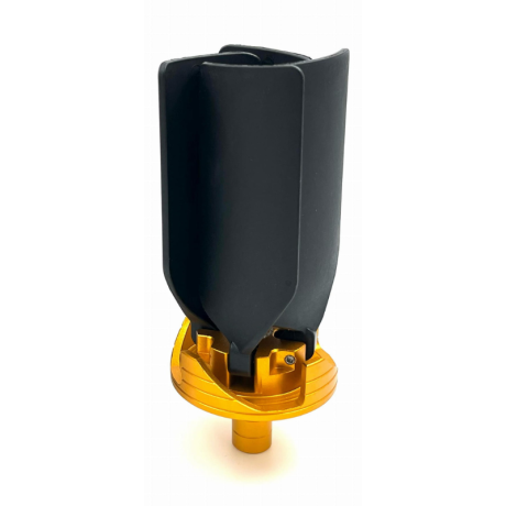
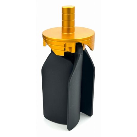 Other Accessories 0.00
CNC Chip Fan / Chip Blower
Complete CNC chip fan Kit: blades, springs, pins and screwsPrice €53.82Price €43.76without VAT -
Bestseller
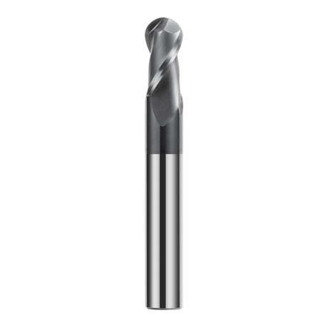
 Ball Nose End Mills 0.00
2-Flute Carbide Ball Nose End Mill - HYPERCUT
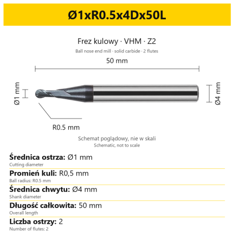
Ø1xR0.5x4Dx50L Ø1.5xR0.75x4Dx50L Ø2xR1x4Dx50L Ø2.5xR1.25x4Dx50L Ø3xR1.5x3Dx50L + 26 morePrice €10.14Price €8.25without VAT -
Bestseller
 2-Flute End Mills 0.00
2-Flute Carbide End Mill for Aluminium
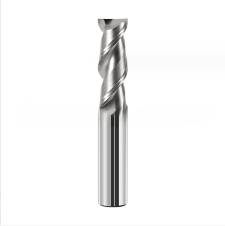
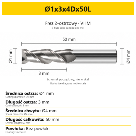
Ø1x3x4Dx50L Ø1.5x4x4Dx50L Ø2x6x4Dx50L Ø2.5x7.5x4Dx50L Ø3x9x3Dx50L + 31 morePrice €5.35Price €4.35without VAT -
Bestseller
 2-Flute End Mills 0.00
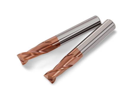
2-Flute Carbide End Mill for Steel 55 HRC - TiSiN - Solid Carbide
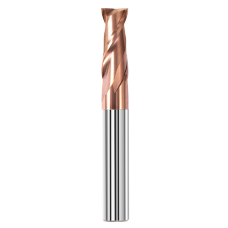
Ø6x24x6Dx75L Ø8x25x8Dx75L Ø4x20x4Dx100L Ø5x30x5Dx100L Ø6x30x6Dx100L + 31 morePrice €4.40Price €3.58without VAT -
Bestseller
 Ball Nose End Mills 0.00
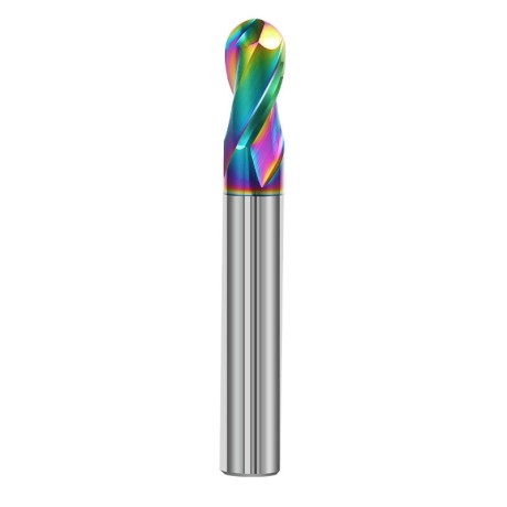
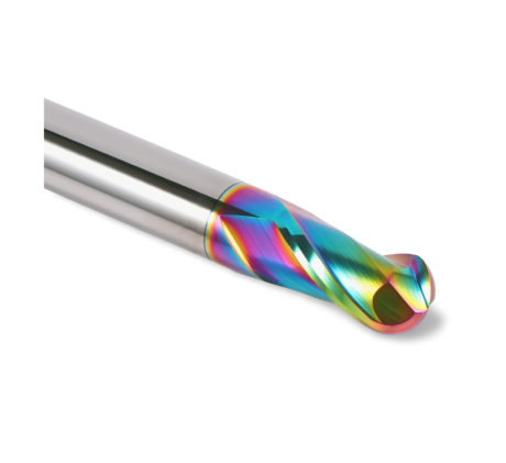
2-Flute DLC Coated Carbide Ball Nose End Mill| DuraEdge Alu
Ø1.0xR0.5x4Dx50L Ø1.5xR0.75x4Dx50L Ø2.0xR1x4Dx50L Ø2.5xR1.25x4Dx50L Ø3.0xR1.5x3Dx50L + 34 morePrice €7.89Price €6.41without VAT -
Bestseller
 2-Flute End Mills 0.00
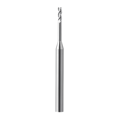
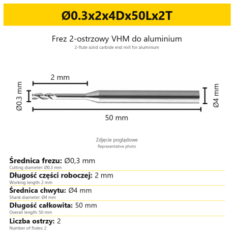
2-Flute End Mill for Aluminium | VHM | Miniature Ø0.3 - Ø0.9
Ø0.3x2x4Dx50Lx2T Ø0.3x3x4Dx50Lx2T Ø0.3x4x4Dx50Lx2T Ø0.4x2x4Dx50Lx2T Ø0.4x3x4Dx50Lx2T + 28 morePrice €7.99Price €6.50without VAT -
Bestseller
 Ball Nose End Mills 0.00
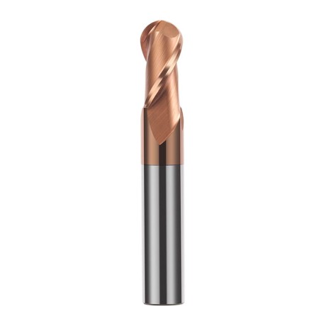
2-Flute TiSiN Coated Carbide Ball Nose End Mill
Ø1xR0.5x4Dx50L Ø1.5xR0.75x4Dx50L Ø2xR1x4Dx50L Ø2.5xR1.25x4Dx50L Ø3xR1.5x3Dx50L + 38 morePrice €7.28Price €5.92without VAT -
Bestseller
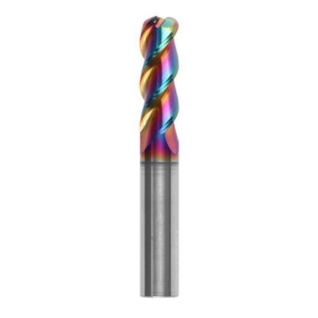
3-Flute Carbide Corner Radius End Mill for Aluminium| AL DLC
Ø1xR0.1x4Dx50L Ø1xR0.2x4Dx50L Ø1xR0.3x4Dx50L Ø1.5xR0.1x4Dx50L Ø1.5xR0.2x4Dx50L + 137 morePrice €4.96Price €4.04without VAT -
Bestseller
3-Flute End Mills 0.00
3-Flute Carbide End Mill VHM Z-3 for Aluminium| TriMill AL
Ø1x3xD4x50L Ø1.5x5x4Dx50L Ø2x6x4Dx50L Ø2.5x8x4Dx50L Ø3x9x3Dx50L + 41 morePrice €5.10Price €4.15without VAT -
Bestseller
 Countersinks 0.00
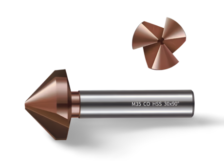
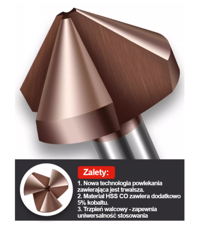
3-Flute Countersink Fi4.5-fi60, 90° - HSS-CO - 5% Kobaltu | Straight Shank
Ø4.5 x 4 x 90° x 40L Ø5 x 5 x 90° x 45L Ø6.3 x 5 x 90° x 45L Ø8.3 x 6 x 90° x 50L Ø10.4 x 6 x 90° x 50L + 12 morePrice €4.81Price €3.91without VAT -
Bestseller
 3-Flute End Mills 0.00
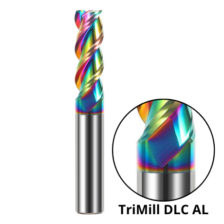
3-Flute DLC Coated Carbide End Mill | TriMill DLC AL
Ø1x3x4Dx50L Ø1.5x5x4Dx50L Ø2x6x4Dx50L Ø2.5x8x4Dx50L Ø3x8x3Dx50L + 38 morePrice €5.07Price €4.12without VAT