€705.27 incl. VAT
Lowest price in the 30 days before the reduction: €796.27
€573.39 excl. VAT
Choose variant


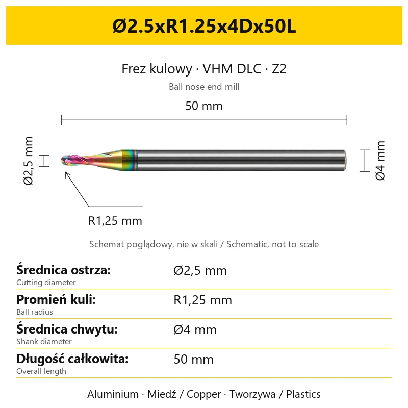
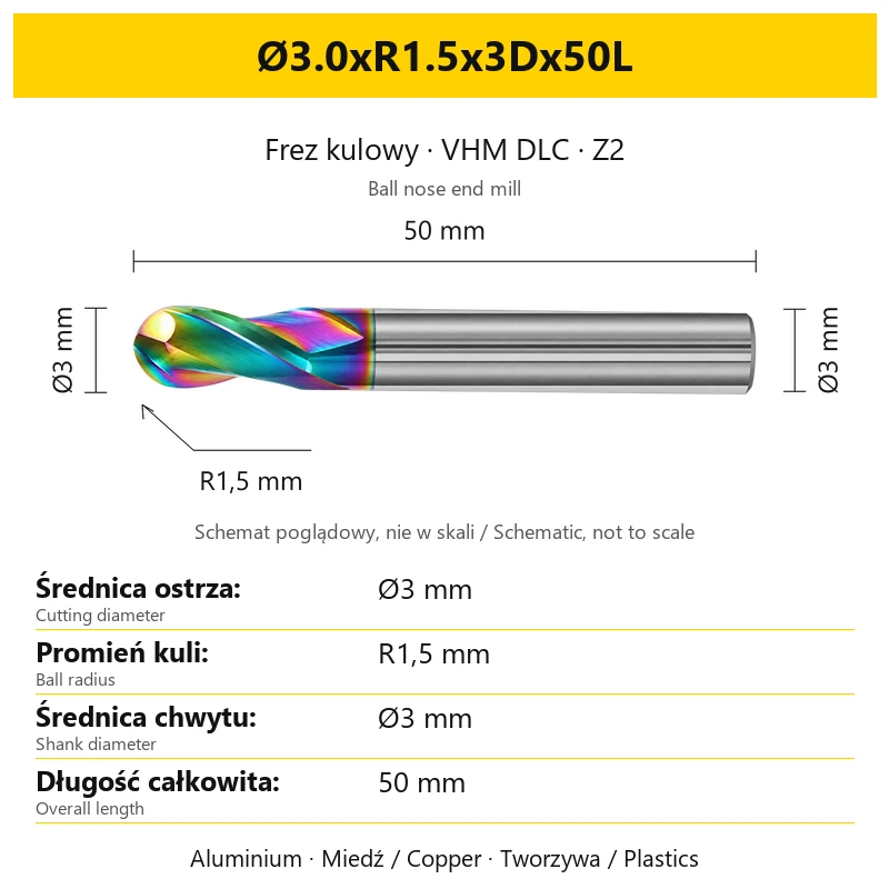
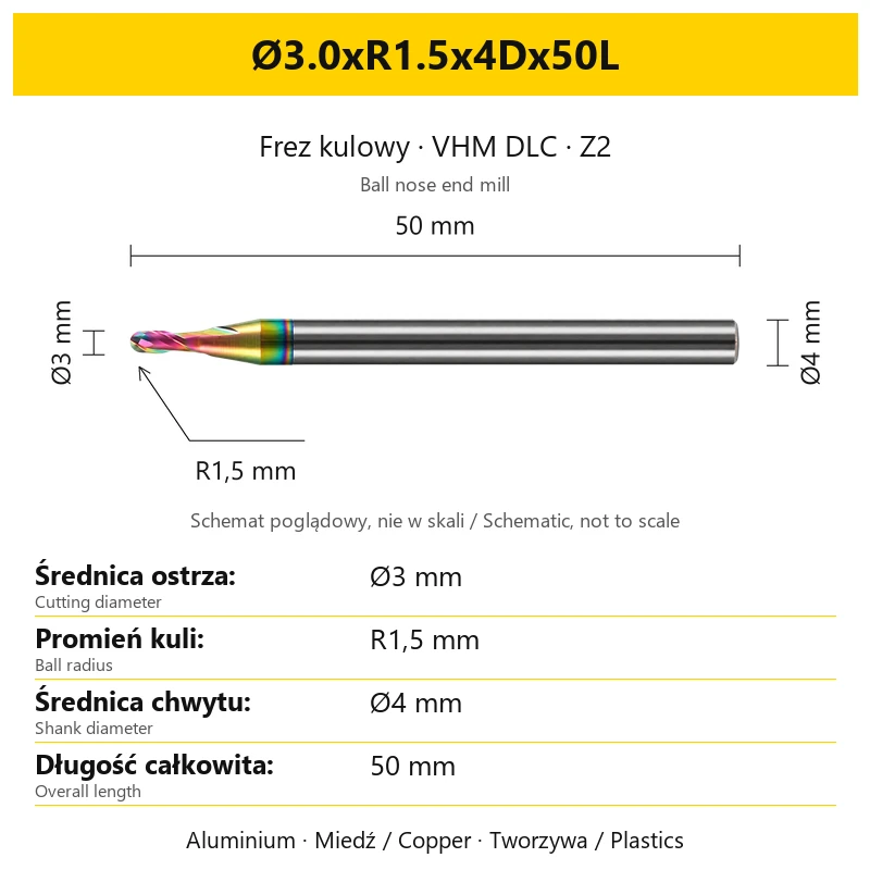
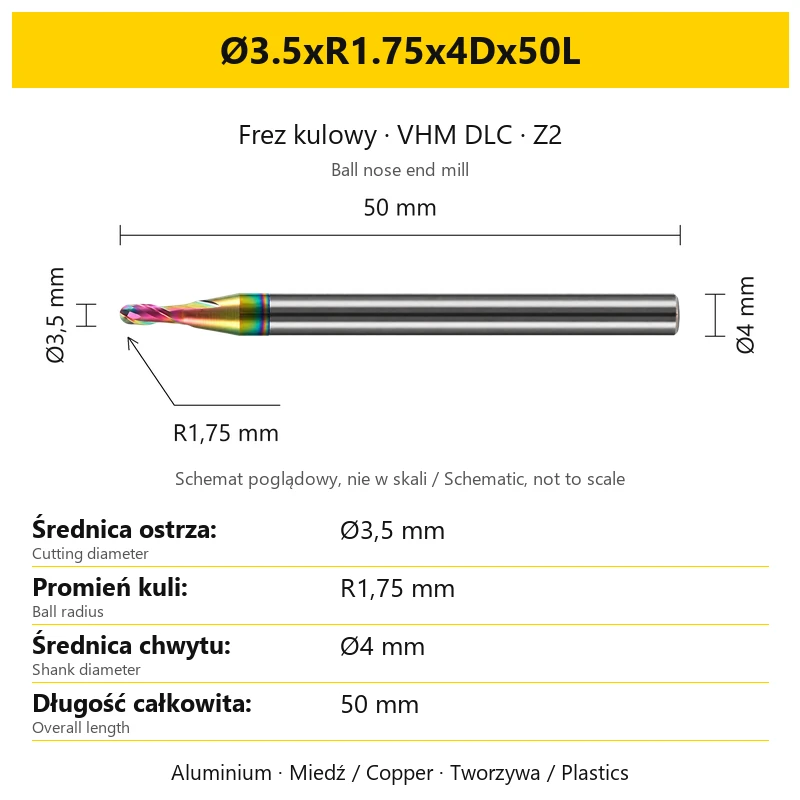
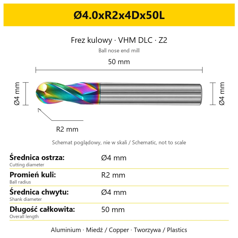
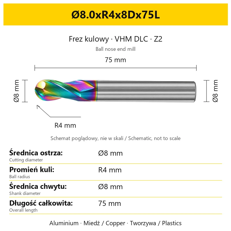
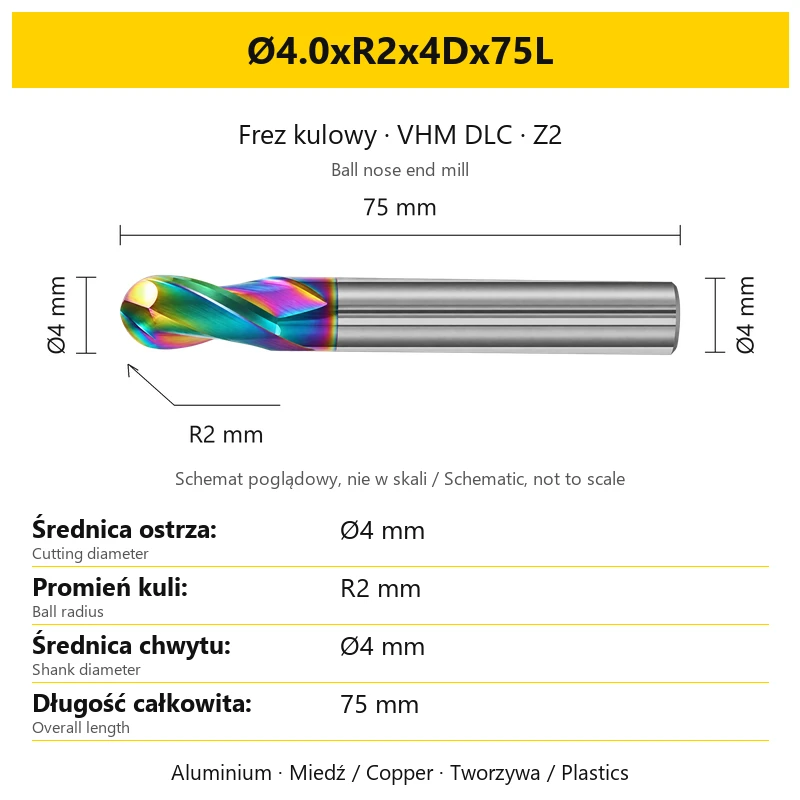
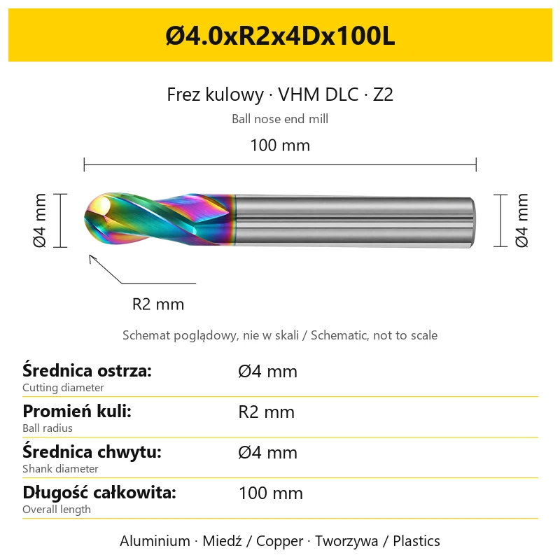
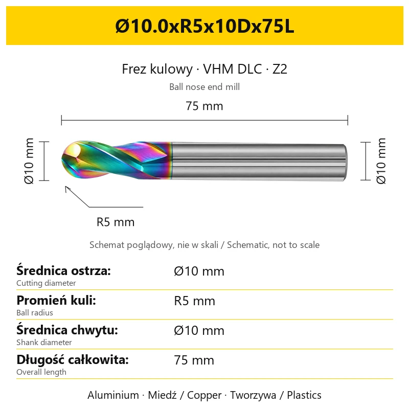
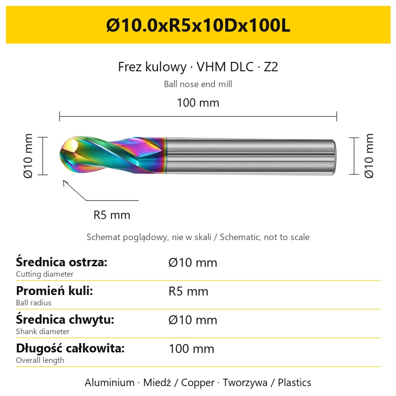
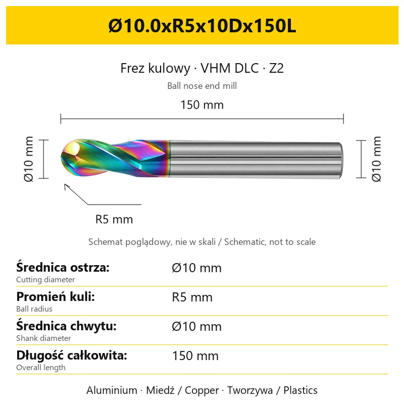
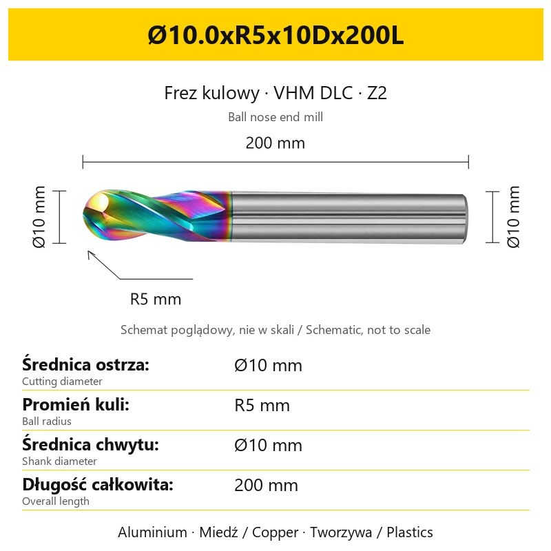
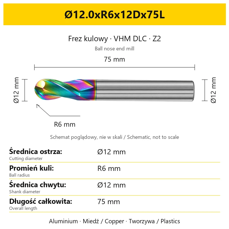
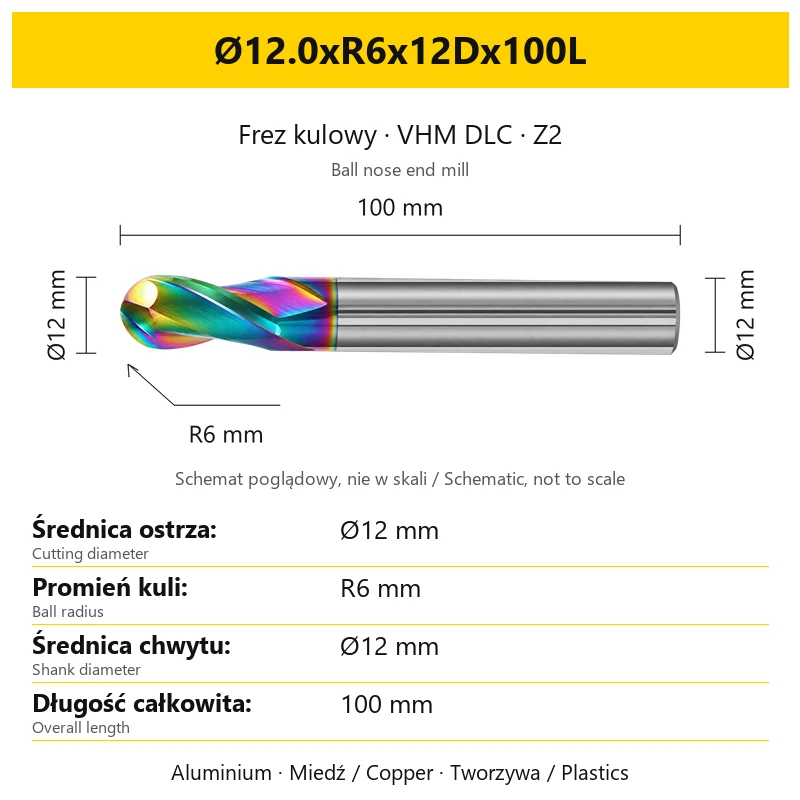
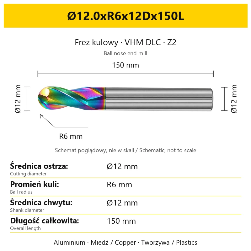
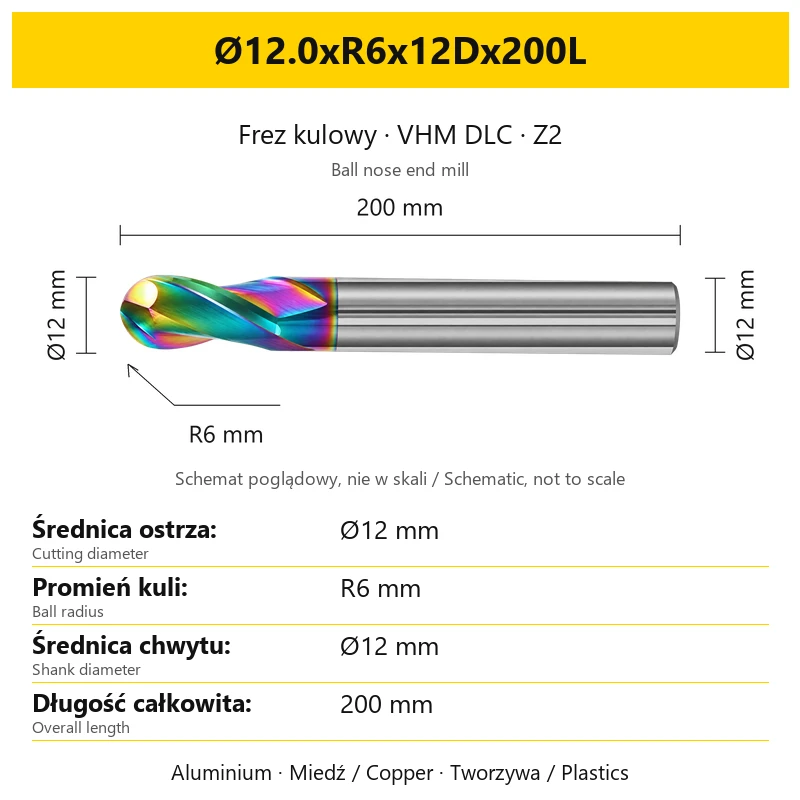
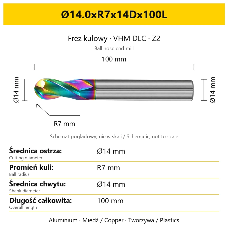
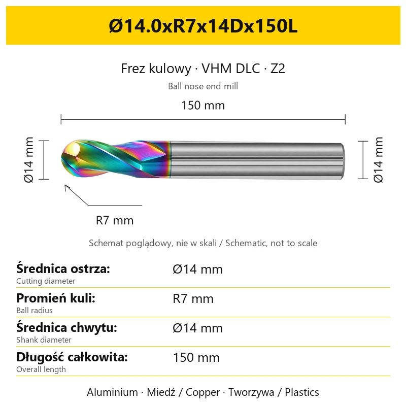
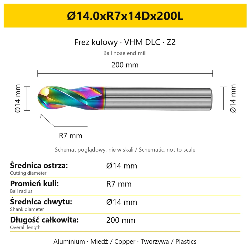
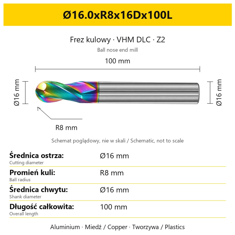
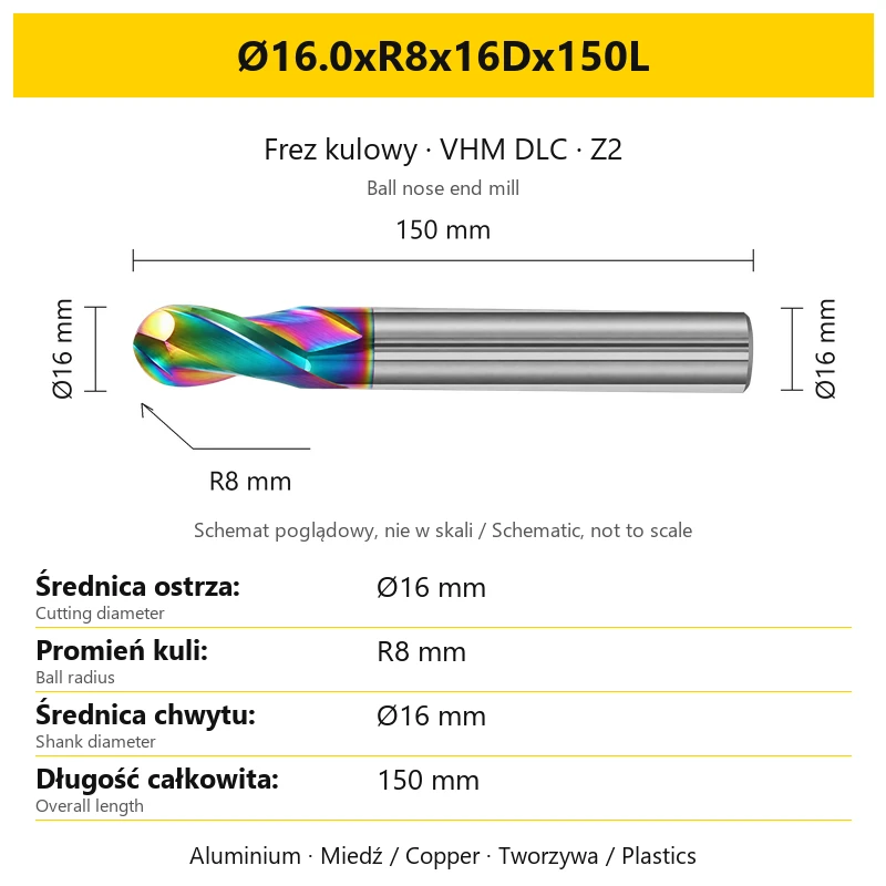
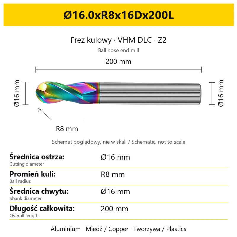
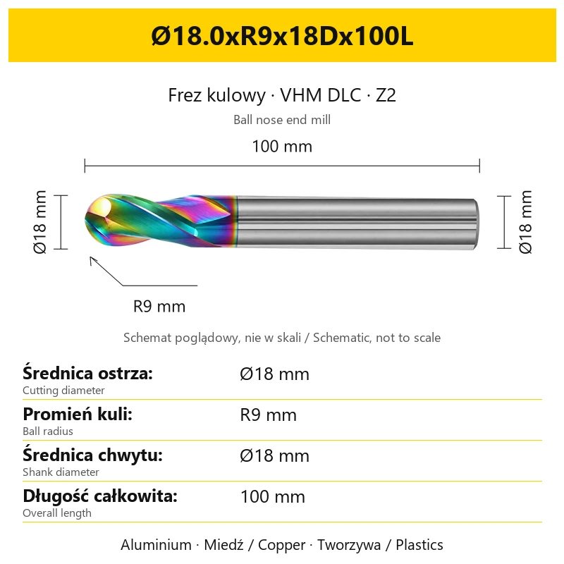
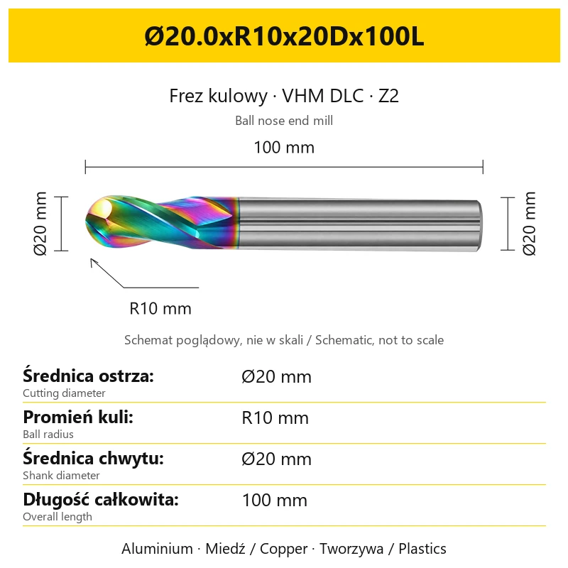
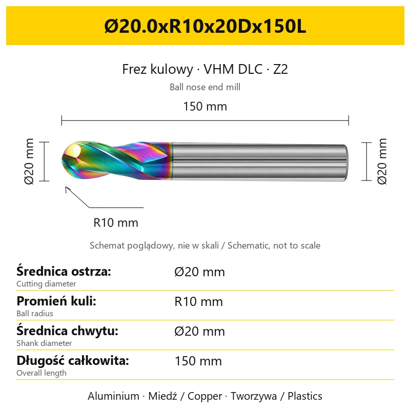
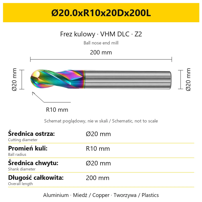
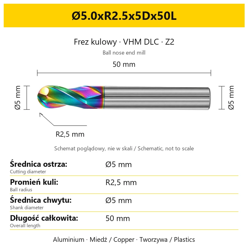
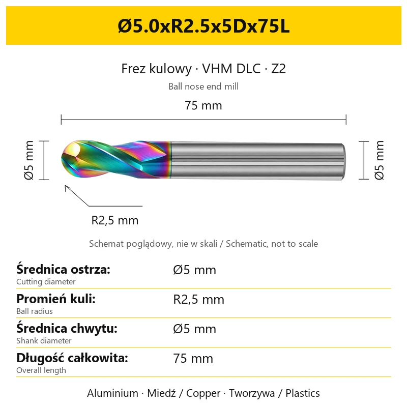
Shipping costs are not included in the price.
Shipping costs are not included in the price.

Weekly deals · −11%
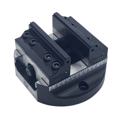
Self-centering machine vise. Hard jaws included.
€573.39 excl. VAT
Regular price: €796.27
Lowest price in the 30 days before the reduction: €796.27
Time left
Offer ends 06.11.2026 23:59. Offer applies to the vise + hard jaws bundle only.
Lowest price in the 30 days before the reduction: €796.27
€573.39 excl. VAT
Choose variant
Weekly deals · −5%
MFPN66-50-22-4T
€47.44 excl. VAT
Regular price: €61.43
Lowest price in the 30 days before the reduction: €61.43
Time left
Offer ends 06.11.2026 23:59.

Weekly deals · −5%
MFPN66-50-22-4T
€57.11 excl. VAT
Regular price: €73.94
Lowest price in the 30 days before the reduction: €73.94
Time left
Offer ends 06.11.2026 23:59.

The administrator of personal data is Kortools. We process it to respond to your inquiry. More information regarding the processing of personal data can be found in privacy policy.
Select a product variant:
Individual variants may differ in price
Product code: 8FFC-93824
DuraEdge Alu DLC-coated solid carbide ball nose end mill, Z2
Two-flute ball nose · geometry for 3D machining and profiled surfaces · for aluminium, copper, plastics and zinc alloys
The DuraEdge Alu solid carbide ball nose end mill has two cutting edges and a DLC coating. It is intended for machining non-ferrous workpieces and plastics. Its spherical end profile follows programmed paths across three-dimensional surfaces, radii, transitions and other contours where a flat-ended tool would not reproduce the same shape.
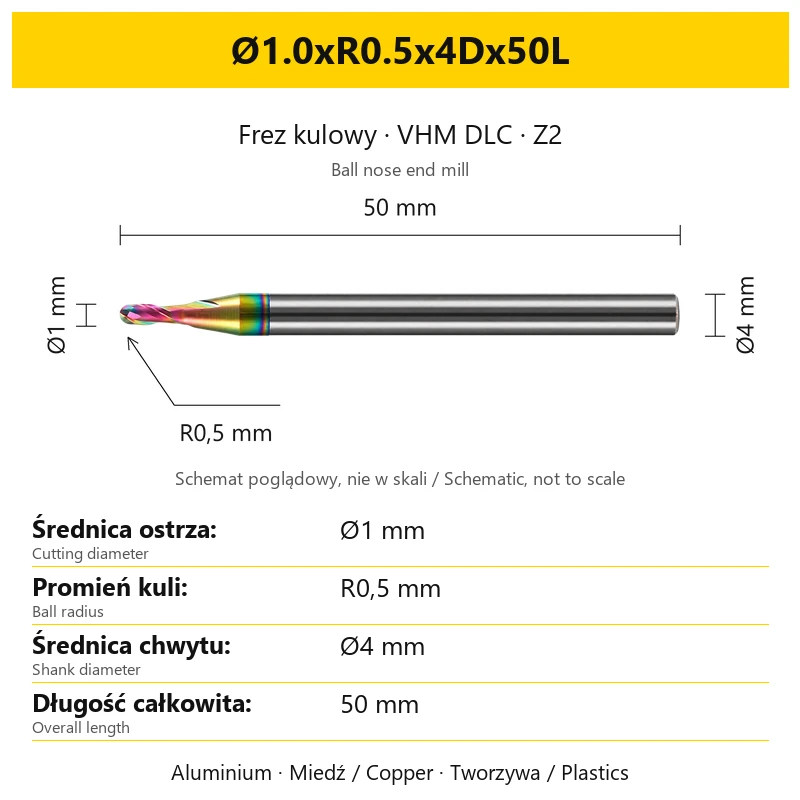
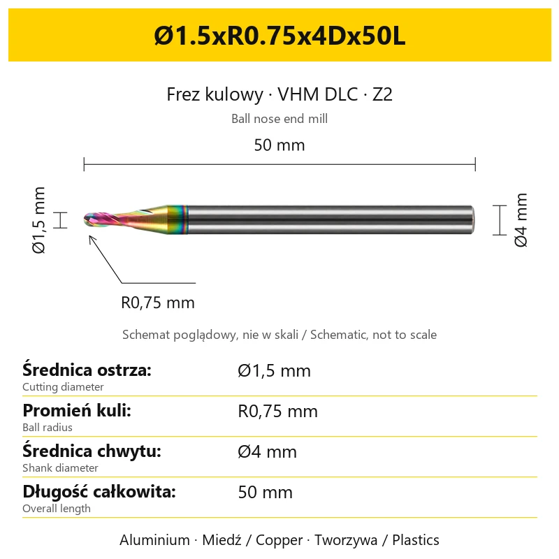
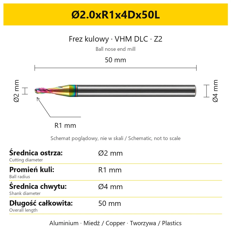
The family covers cutting diameters from Ø1 to Ø20 mm, ball radii from R0.5 to R10 mm, shank diameters from Ø3 to Ø20 mm, and overall lengths of 50, 60, 75, 100, 150 and 200 mm. These are family ranges; select the exact dimension combination in the variant selector.
The tool end has a spherical profile. As the cutter follows a programmed path, the contact point moves around the ball as the surface inclination changes. This geometry is used for finishing profiled surfaces, mould forms, recesses, smooth transitions and spatial contours on CNC milling machines.
Both cutting edges extend through the centre of the end, and the helix angle is 35°. Z2, centre-cutting geometry and the spherical profile describe the tool construction; they do not define one universal set of cutting data for every machine, diameter and workpiece group.
The application range includes aluminium and aluminium alloys, copper and copper alloys, zinc alloys, PMMA / acrylic, PVC, PE, PTFE and other plastics. Wood is a secondary application rather than a primary workpiece group for this family.
| Workpiece group or operation | Application |
|---|---|
| Aluminium and aluminium alloys | Milling profiled surfaces, radii, transitions and three-dimensional forms. |
| Copper and copper alloys | Form machining and finishing along programmed CNC paths. |
| Zinc alloys | Surface and profile machining with conditions selected for the particular alloy. |
| PMMA / acrylic | Forming and finishing 3D surfaces with effective chip evacuation. |
| PVC, PE, PTFE and other plastics | Contour and profile machining with conditions adapted to the cutting behaviour of the specific polymer. |
| Wood | A secondary application when the ball nose geometry suits the required profile. |
| 3D machining and profiled surfaces | Guiding the spherical end along paths prepared in the CNC program. |
| Finishing | Final passes across radii, recesses and surfaces with changing inclination. |
Select the end mill to match both the workpiece group and the geometry of the surface to be machined. This series is intended primarily for the listed non-ferrous workpieces and plastics.
| Parameter | Specification |
|---|---|
| Tool type | Ball nose end mill, two-flute ball nose |
| Series | DuraEdge Alu |
| Tool substrate | VHM — solid carbide |
| Coating | DLC |
| Flute count | 2 — Z2 |
| End profile | Ball nose |
| Centre geometry | Cutting edges extend through the centre |
| Helix angle | 35° |
| Carbide grain size | 0.6 µm |
| Shank | Cylindrical; diameter depends on the selected variant |
| Workpiece groups | Aluminium, copper, PMMA / acrylic, PVC, PE, PTFE, other plastics and zinc alloys; wood as a secondary use |
| Machine application | CNC milling machines, machining centres and engraving machines with suitable clamping |
Cutting diameter, ball radius, shank diameter and overall length depend on the selected variant.
| Dimension | Family range | Selection check |
|---|---|---|
| Cutting diameter D | Ø1–20 mm | Defines the full ball diameter and access to the profiled surface. |
| Ball radius R | R0.5–10 mm | Half the diameter: D = 2R. |
| Shank diameter | Ø3–20 mm | Must match the tool holder or collet. |
| Overall length L | 50, 60, 75, 100, 150 or 200 mm | Describes the complete tool from the end to the back of the shank; relevant to reach and overhang. |
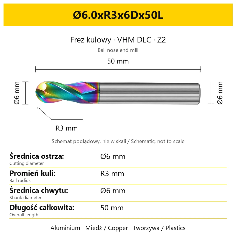
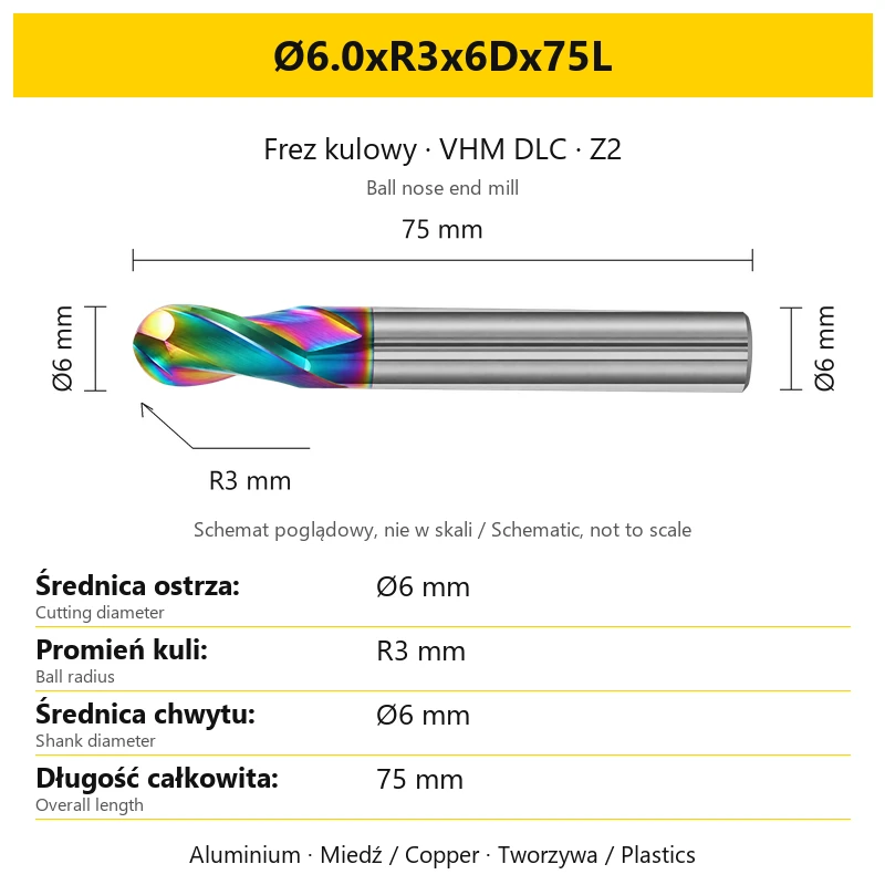
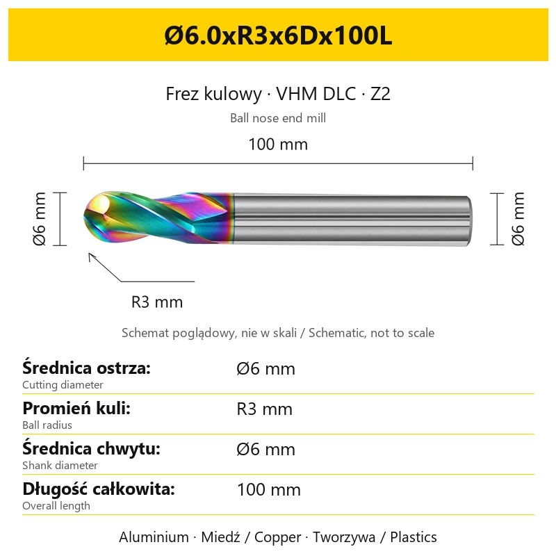
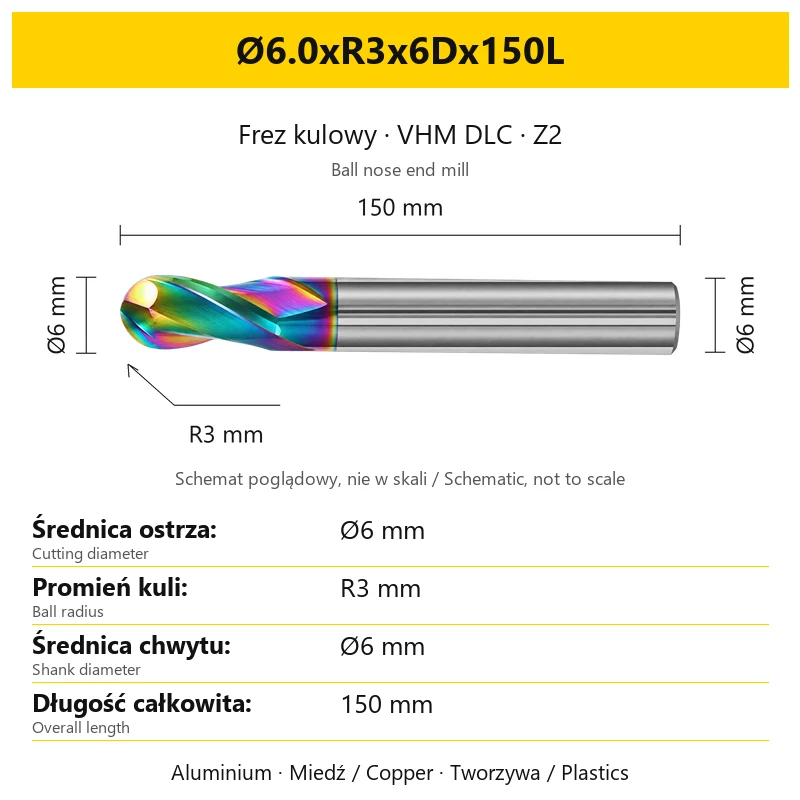
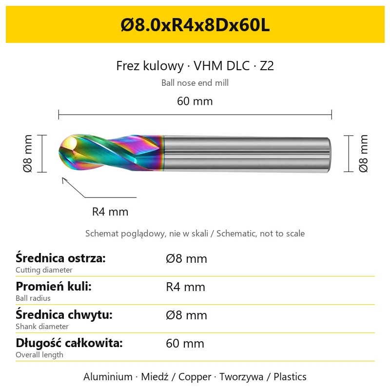
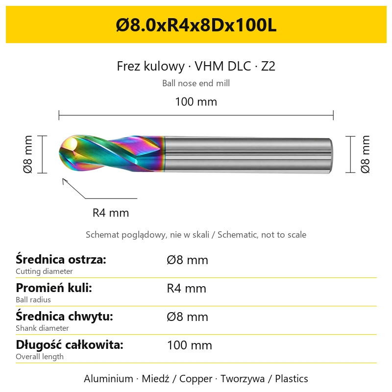
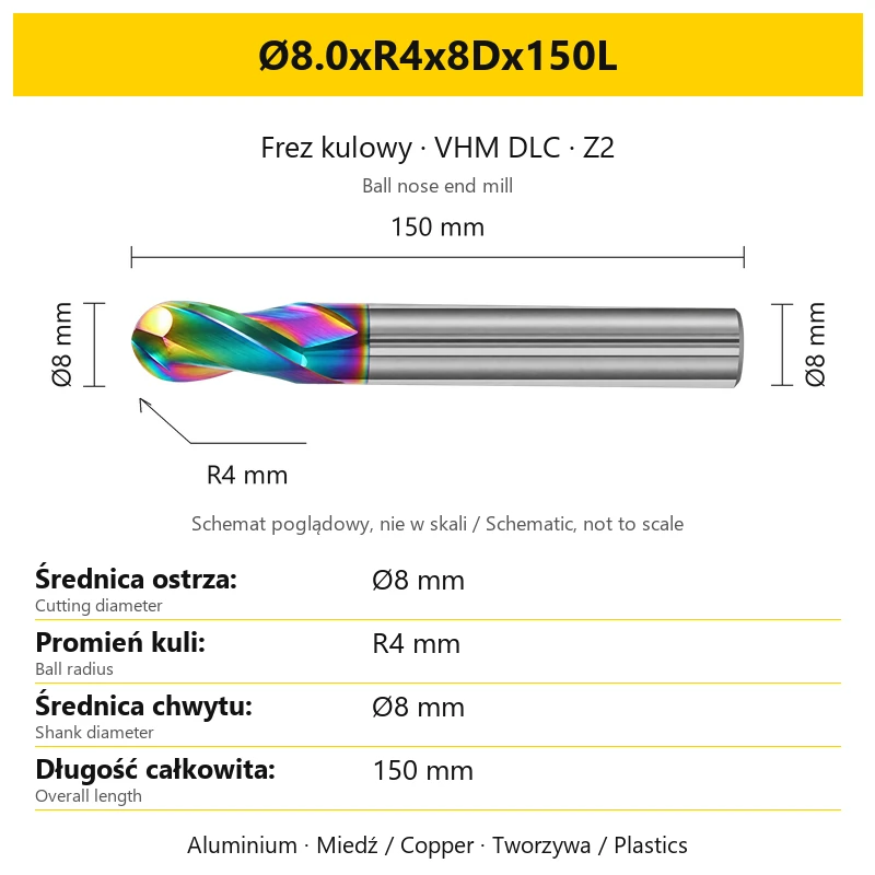
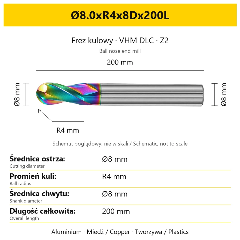
Example: Ø6.0xR3x6Dx50L. The designation combines four items needed to select a ball nose end mill. All dimensions are in millimetres.
| Designation part | Meaning | Example value |
|---|---|---|
| Ø6.0 | Cutting diameter D | 6 mm |
| R3 | Ball nose radius | 3 mm |
| 6D | Shank diameter | 6 mm |
| 50L | Overall tool length | 50 mm |
The first value and the radius describe the same ball in two ways: diameter is twice the radius. R3 does not mean a 3 mm diameter; it corresponds to Ø6 mm. The D after the third value identifies the shank diameter, while L after the final value identifies the complete tool length.
Before machining, confirm that the selected variant matches the holder, inspect the cutting edges, seat the shank correctly and secure the workpiece rigidly. A long tool should not project from the holder further than access to the surface requires. Actual overhang is part of the machining setup.
| Item | Selection scope |
|---|---|
| Sales unit | 1 DuraEdge Alu DLC-coated solid carbide ball nose end mill, Z2 |
| Size | One variant selected in the selector and defined by diameter D, radius R, shank diameter and overall length L |
| Coating and geometry | DLC, Z2, 35° helix and centre-cutting edges |
| Check before ordering | Compare the full designation with the required ball diameter, radius, holder and reach |
| Quantity | The number of pieces of the selected variant entered for the order |
Before adding the product to the basket, check D = 2R, the shank diameter and the L value. This separates the ball size from the clamping dimension and the complete tool length.
No. R3 is a 3 mm radius, corresponding to a Ø6 mm ball diameter. For a ball nose end mill, D = 2R.
They are overall tool lengths, identified by the letter L.
Aluminium and its alloys, copper and its alloys, zinc alloys, PMMA / acrylic, PVC, PE, PTFE and other plastics. Wood is a secondary application.
No. They are separate dimensions. The ball diameter defines the cutting part, while the shank diameter must match the holder or collet. Always check both parts of the variant designation.
Both cutting edges reach the central zone of the spherical end. It is a geometry feature of this Z2 family.
Use the variant selector. Read the ball diameter, radius, shank diameter and overall length in sequence, for example Ø6.0xR3x6Dx50L.


Cookies and related technologies allow the website to function properly and help us adjust the offer to your needs. You can choose to accept our use of all these files and go to the store, or adapt the use of files to your preferences by selecting "Customize Consents".
Here you can define your preferences regarding the use of cookies.
These files are necessary for our website to function so they can't be switched off.
These files allow you to use other functions of the website (other than those necessary for its functioning). Enabling these files will give you access to the full functionality of the website.
These files allow us to analyze our online store, which may contribute to its better functioning and adaptation to the needs of our Users.
With these files, we can conduct marketing activities.