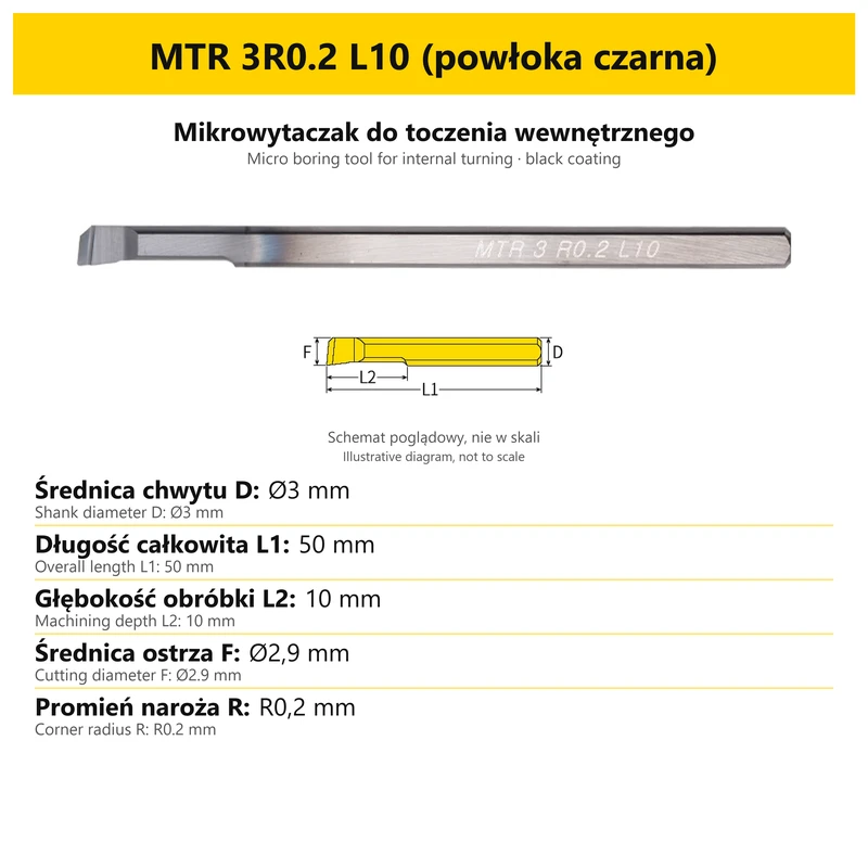
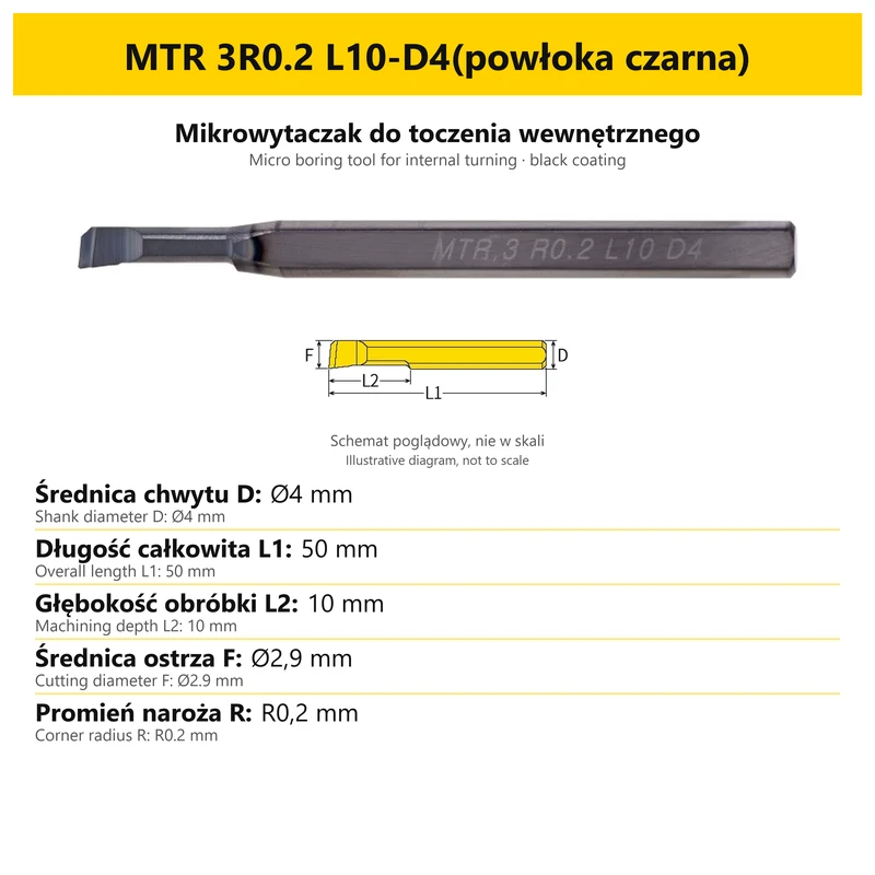
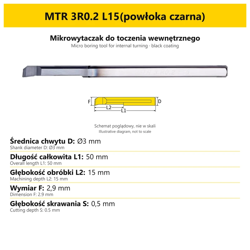
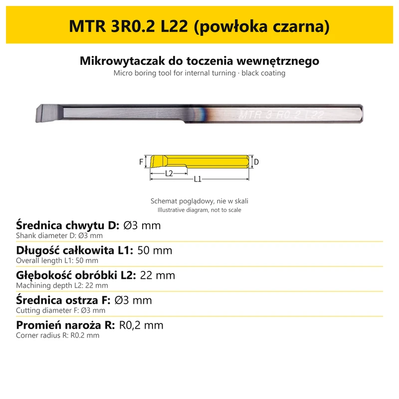
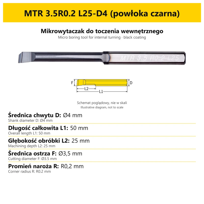
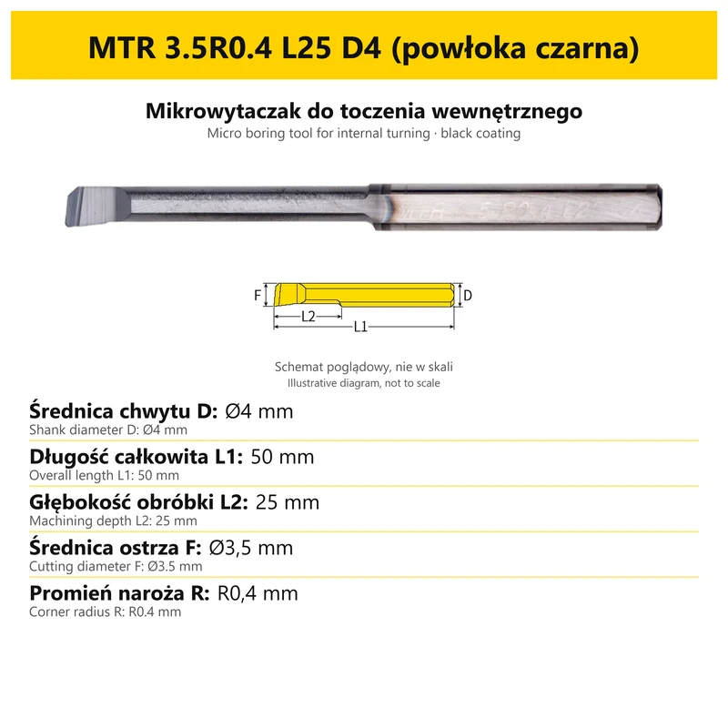
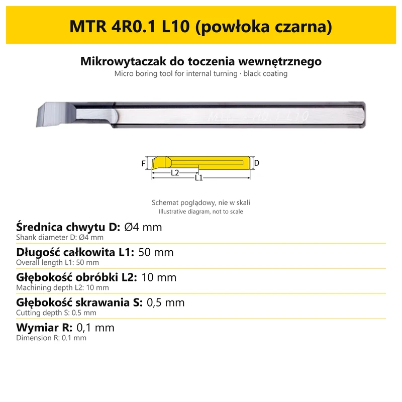
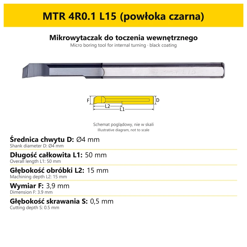
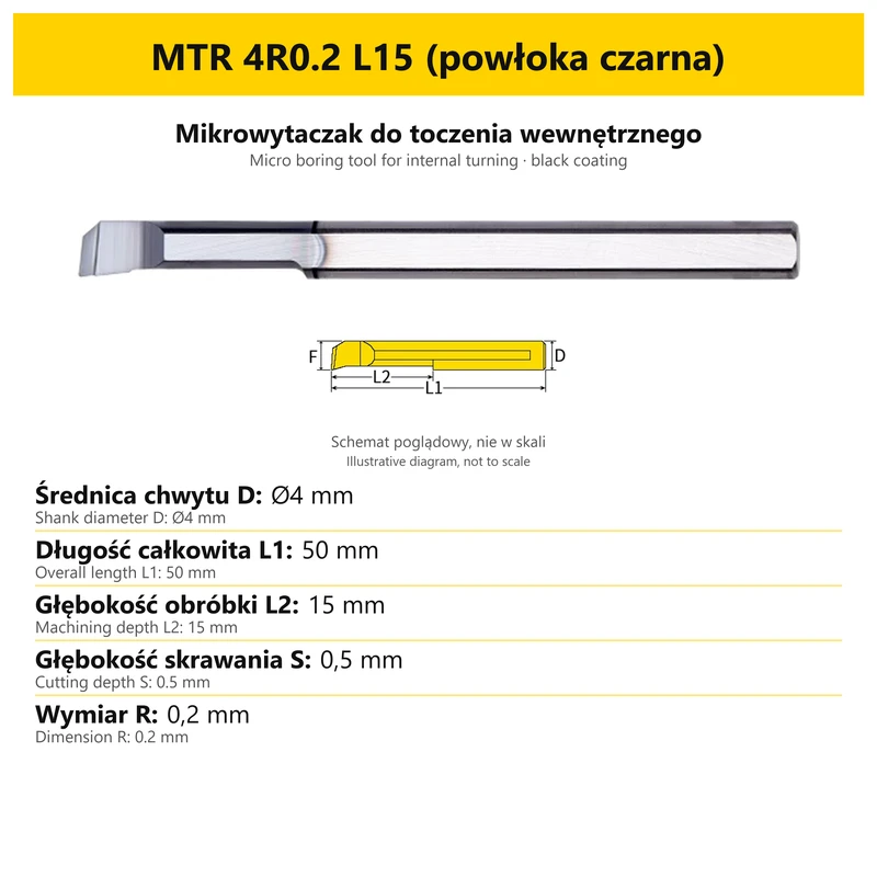
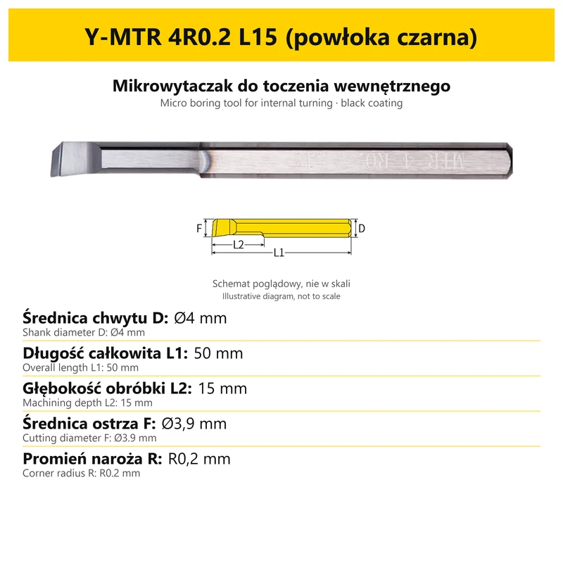
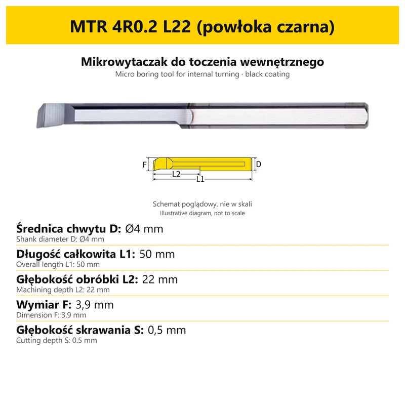
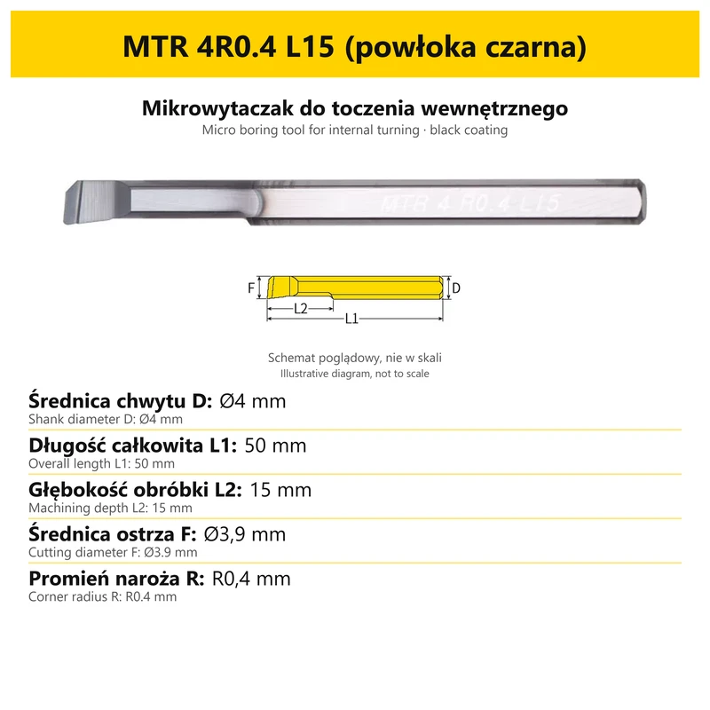
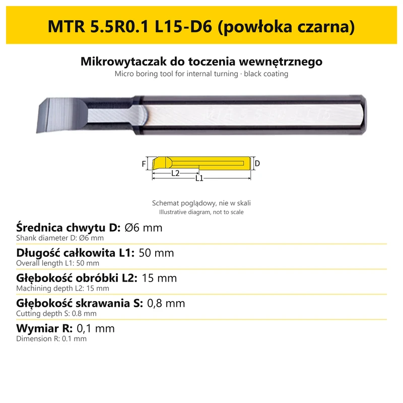
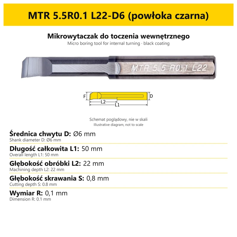
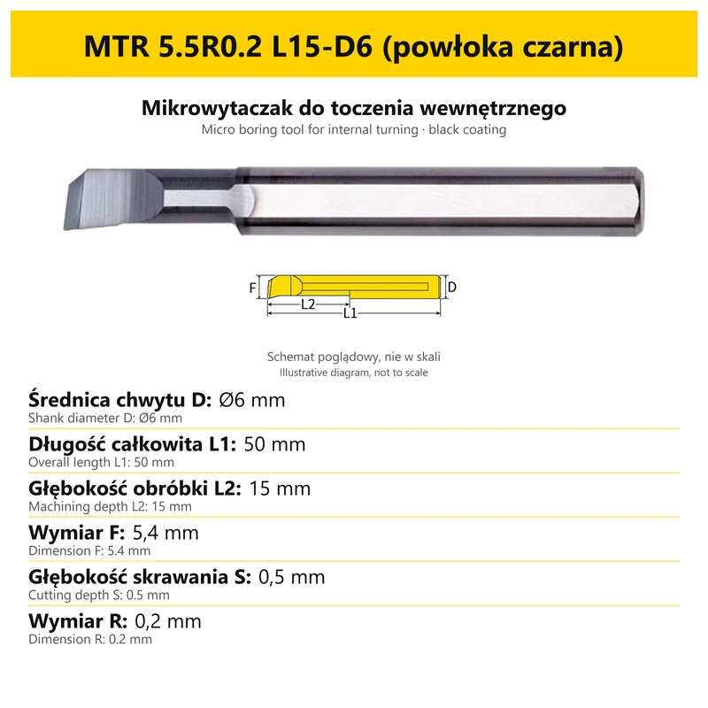
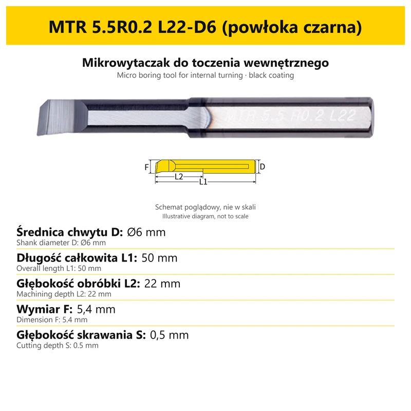
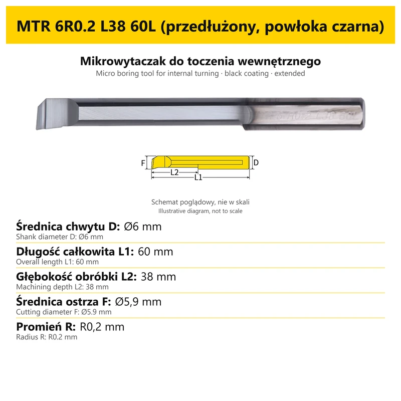
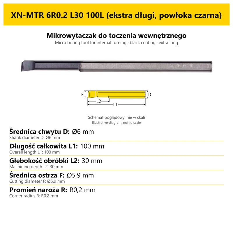
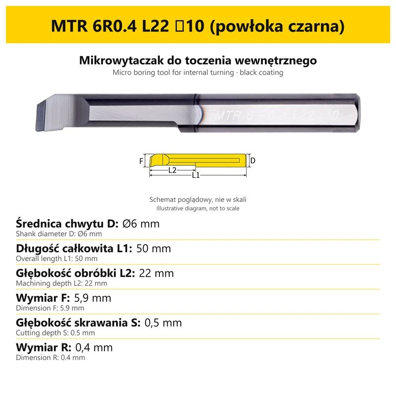
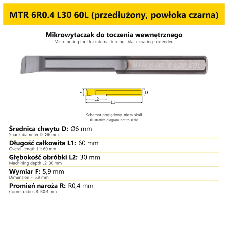
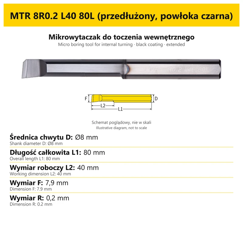
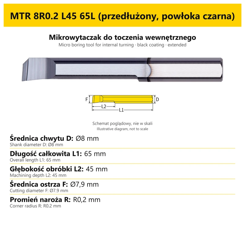
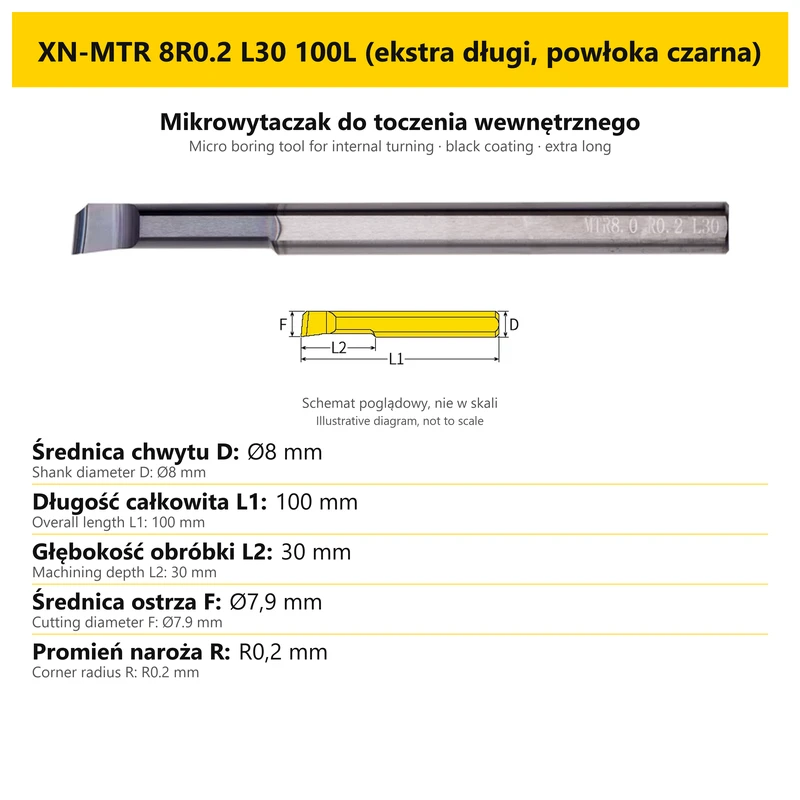
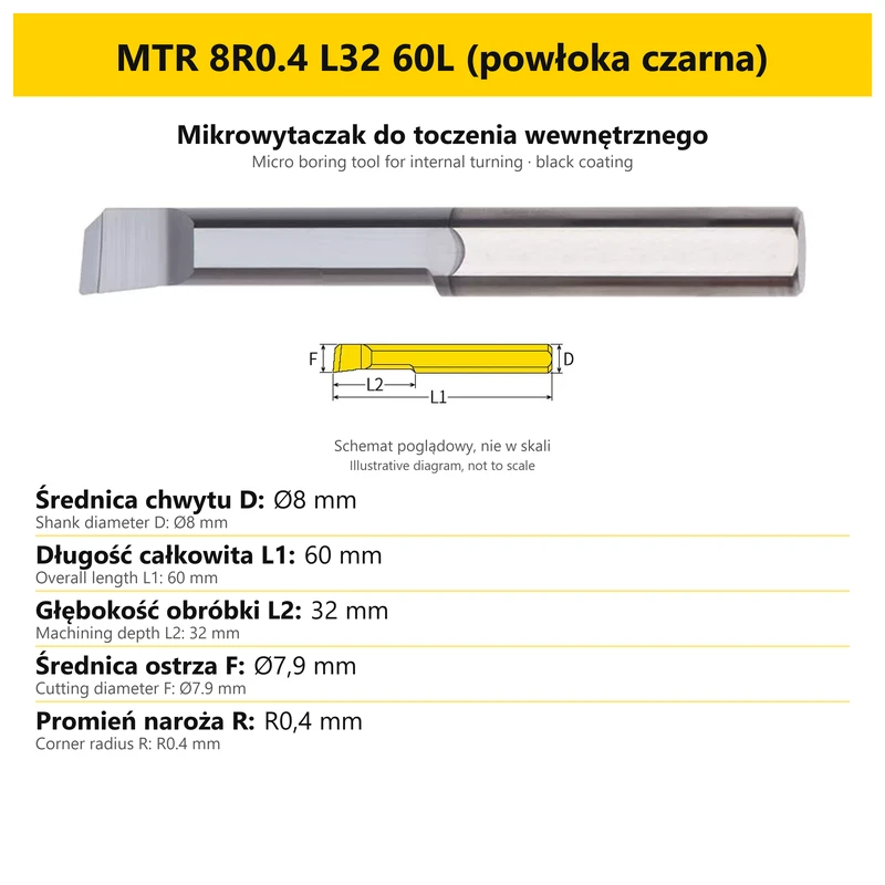
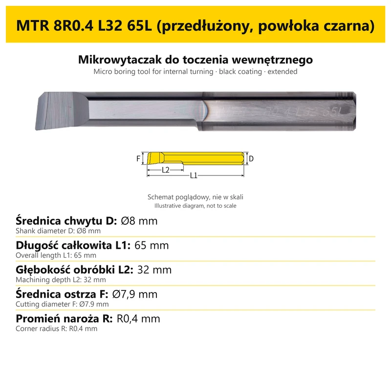


MTR carbide micro boring bar for internal boring
Shipping costs are not included in the price.
Shipping costs are not included in the price.

Weekly deals
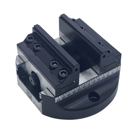
5-axis vise with hard jaws
Self-centering machine vise. Hard jaws included.
excl. VAT
Regular price:
Lowest price in the 30 days before the reduction:
Time left
Offer ends 06.11.2026 23:59. Offer applies to the vise + hard jaws bundle only.
Ask about the product

The administrator of personal data is Kortools. We process it to respond to your inquiry. More information regarding the processing of personal data can be found in privacy policy.
Select a product variant:
Individual variants may differ in price
Product code: 36DE-A0C10
Product description
MTR solid carbide micro tool
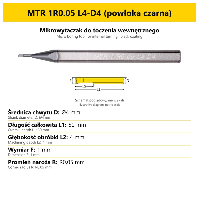
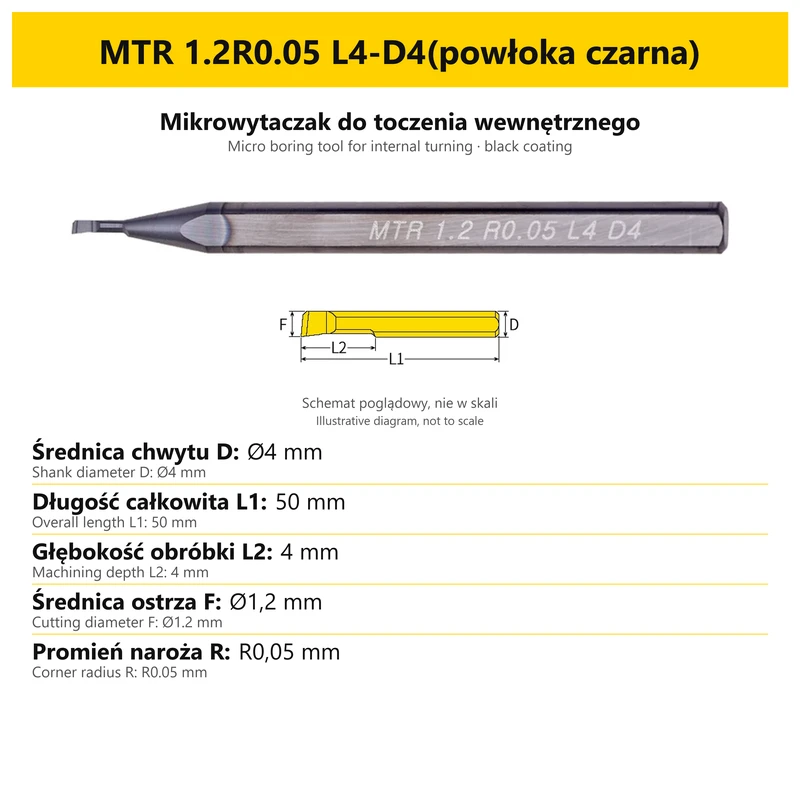
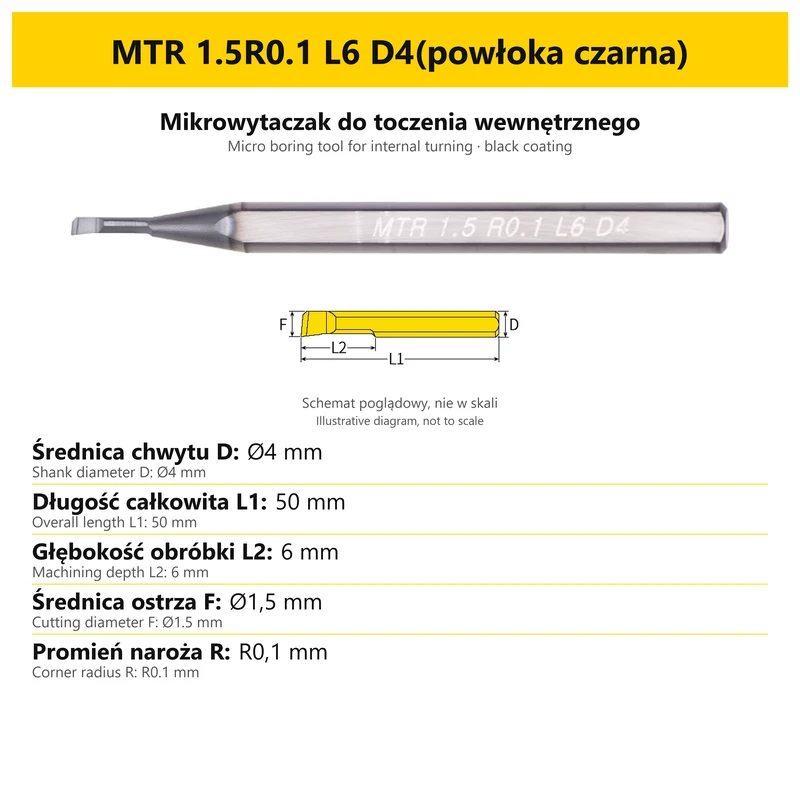
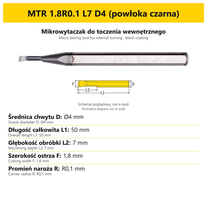
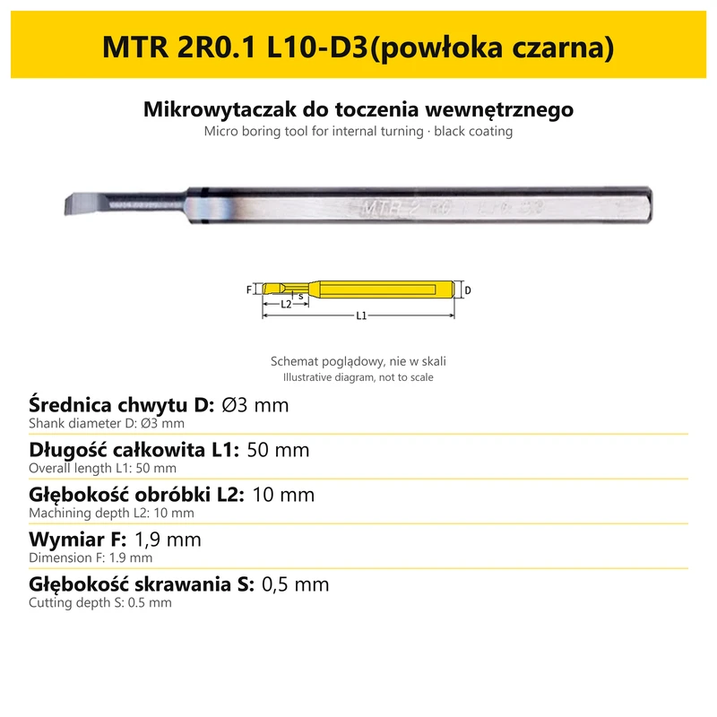
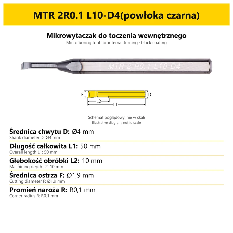
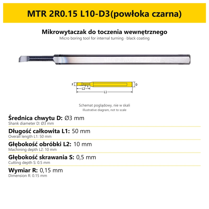
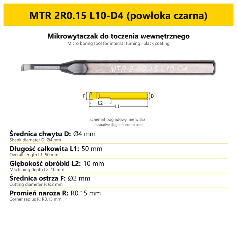
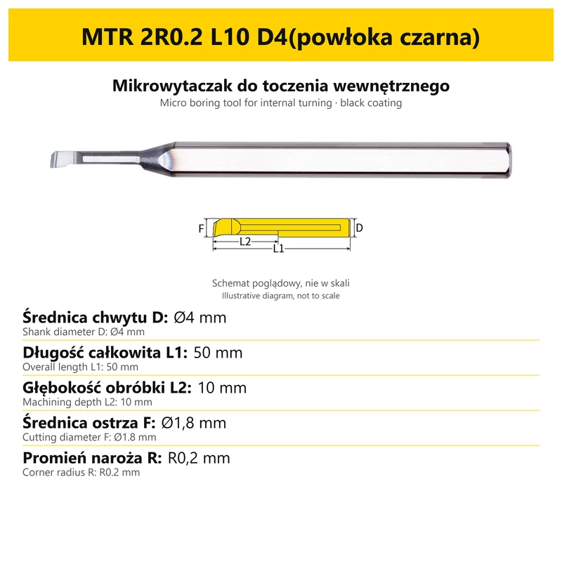
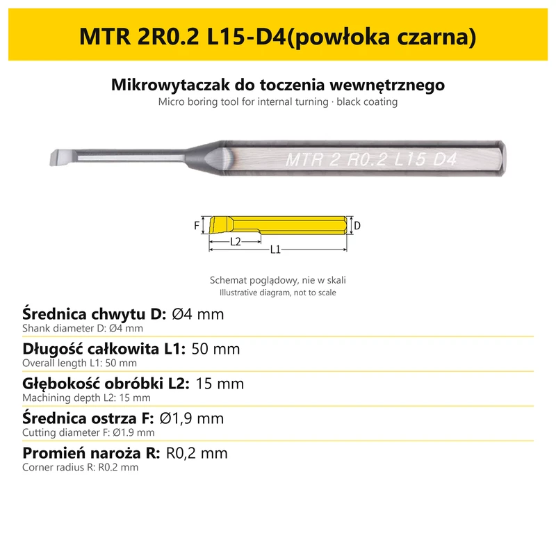
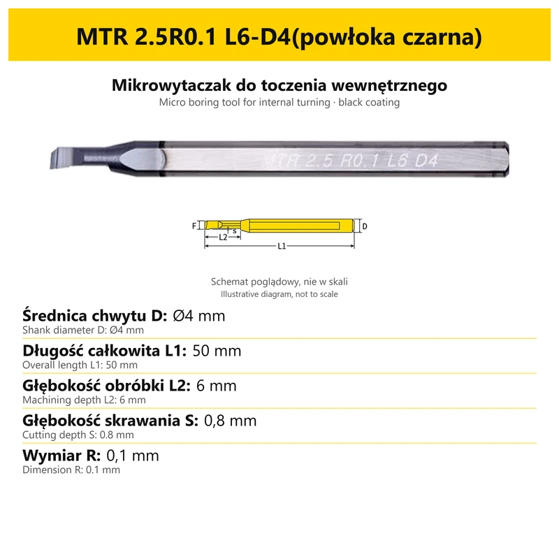
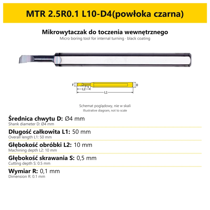
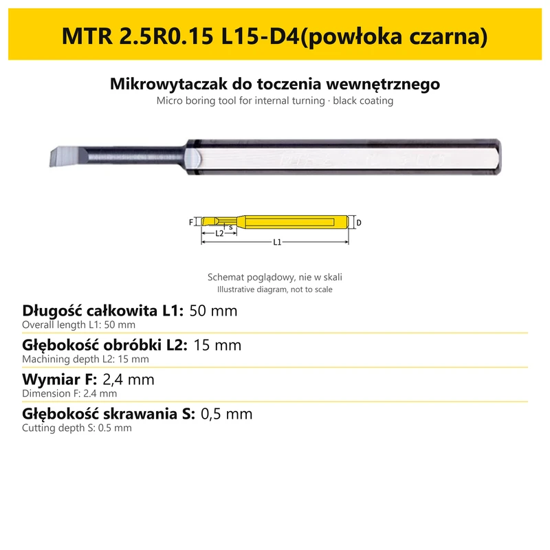
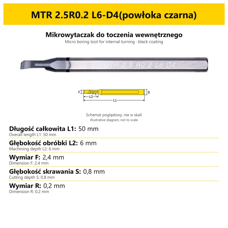
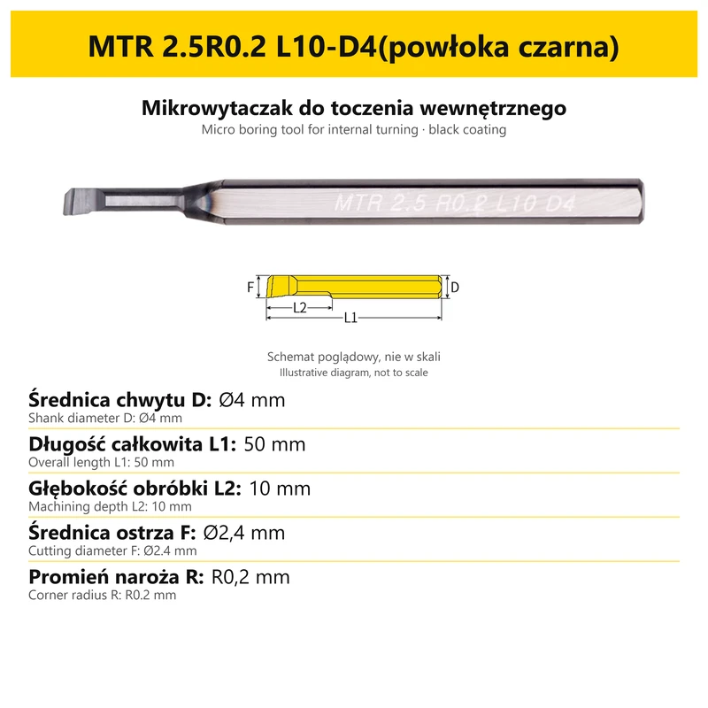
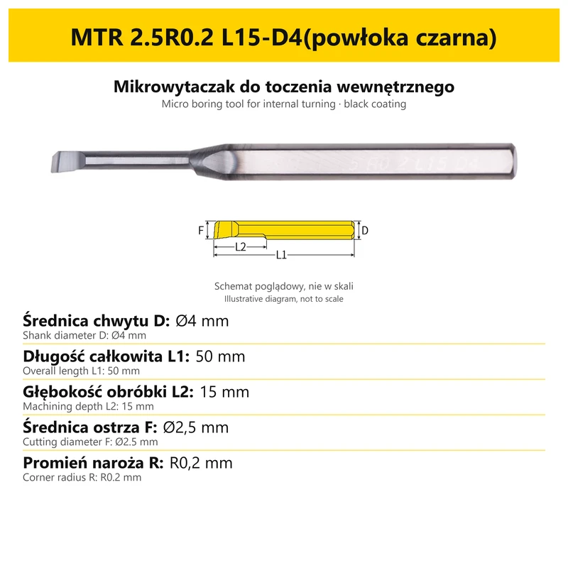
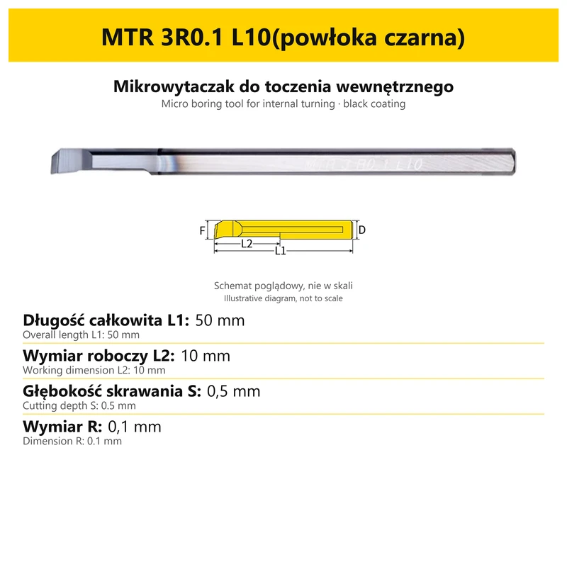
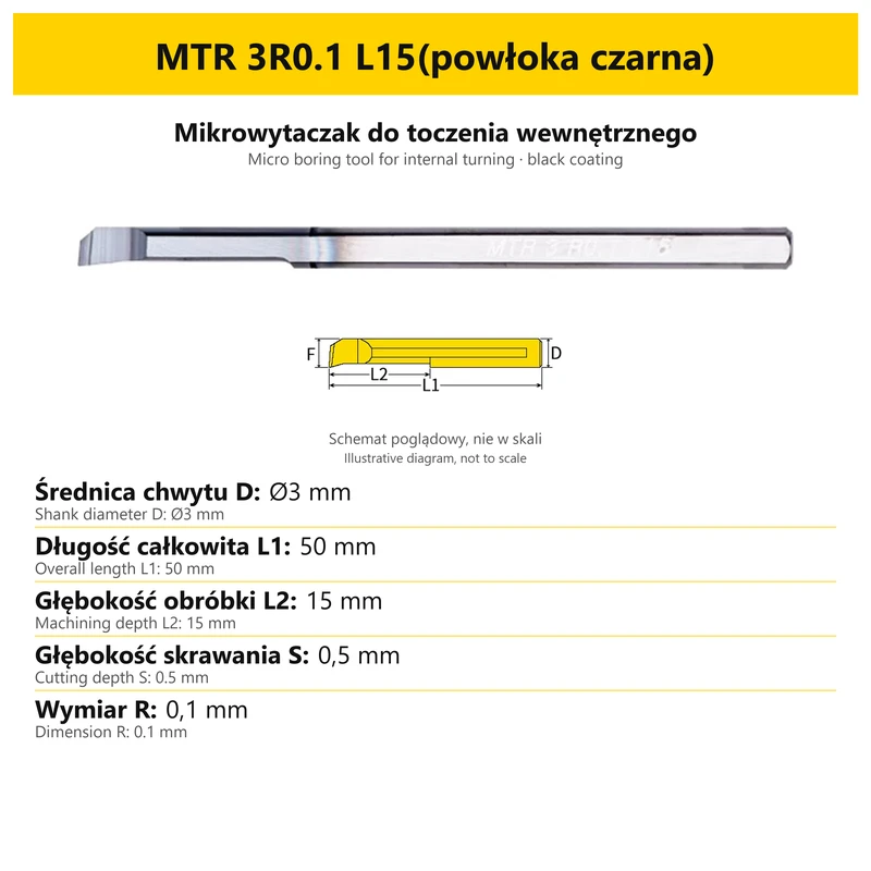
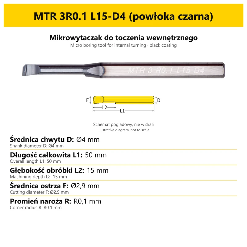
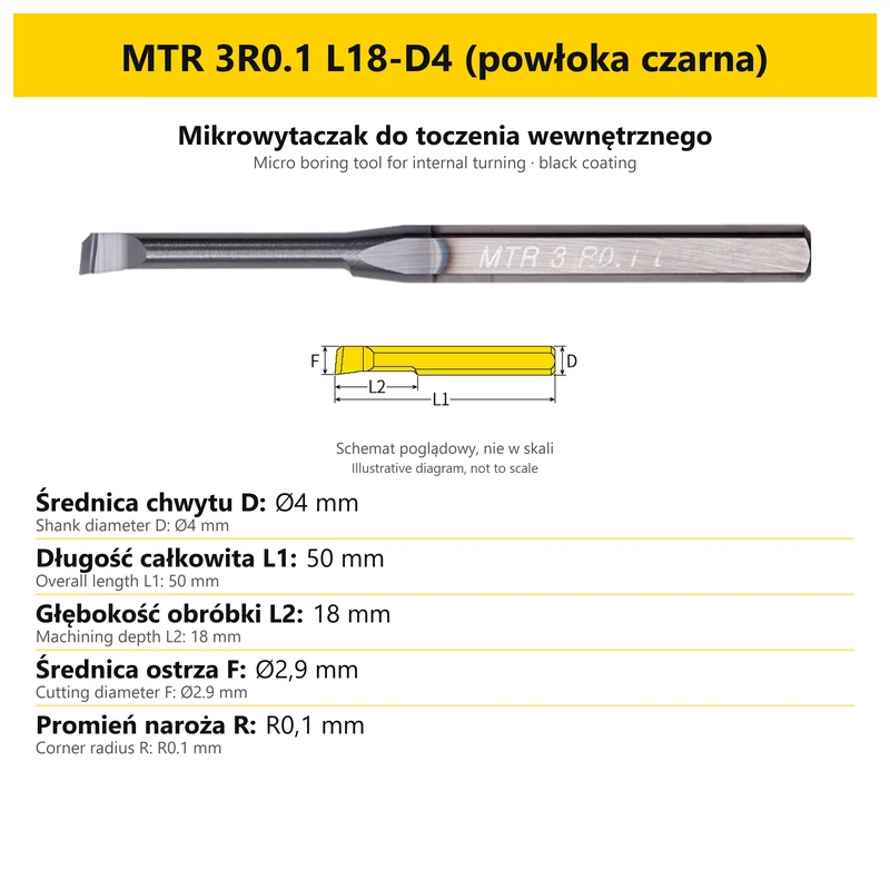
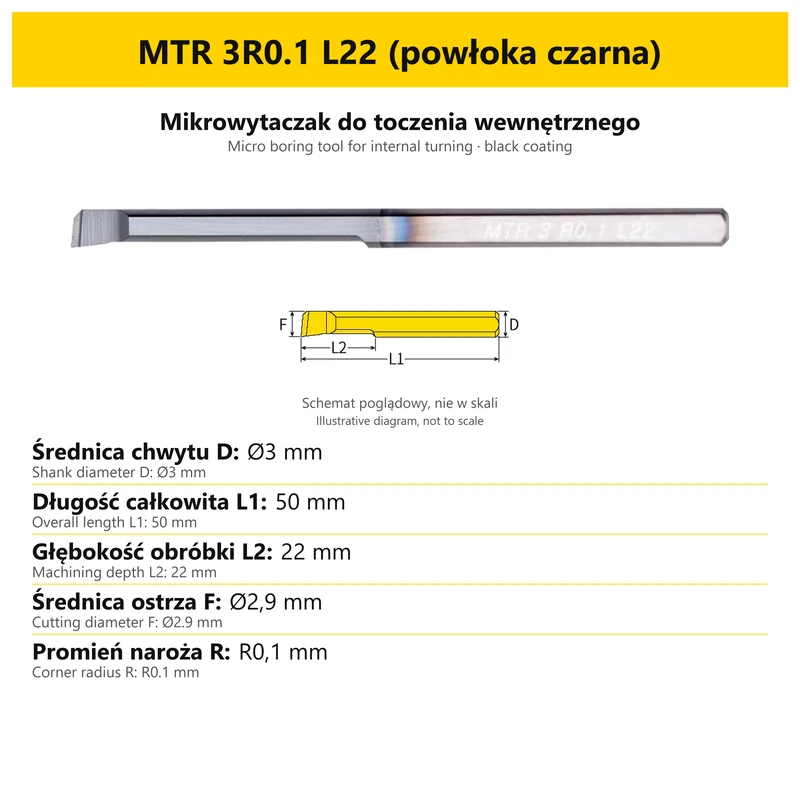
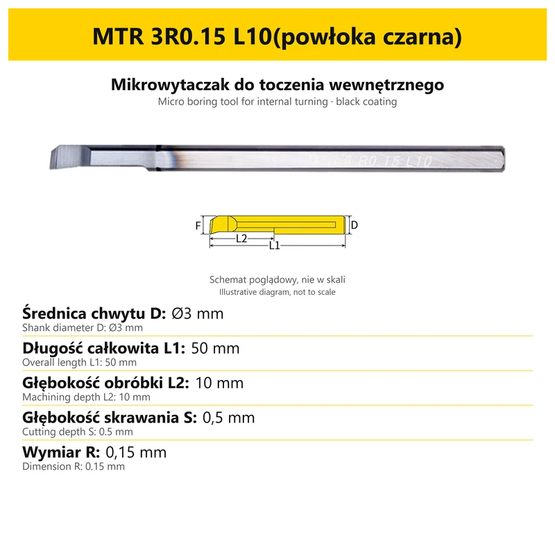
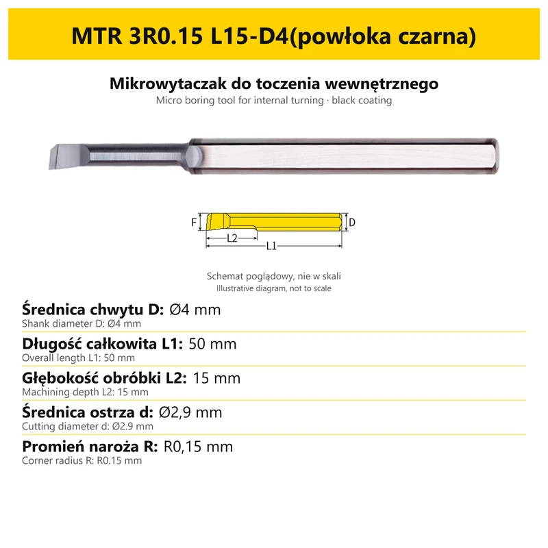
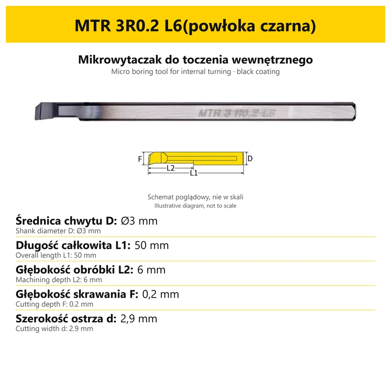
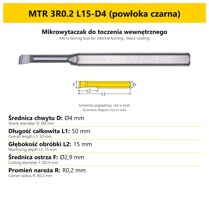
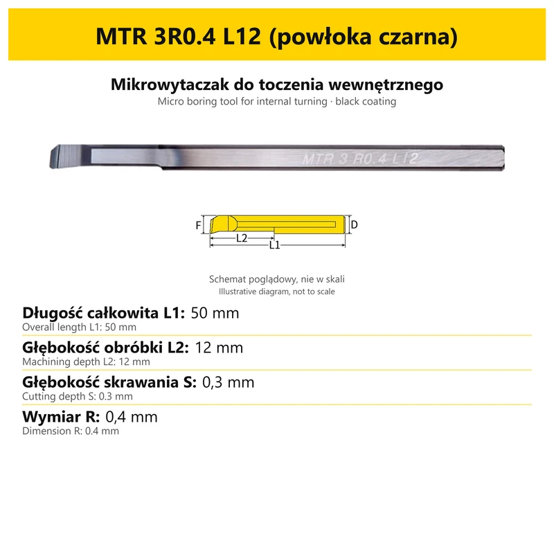
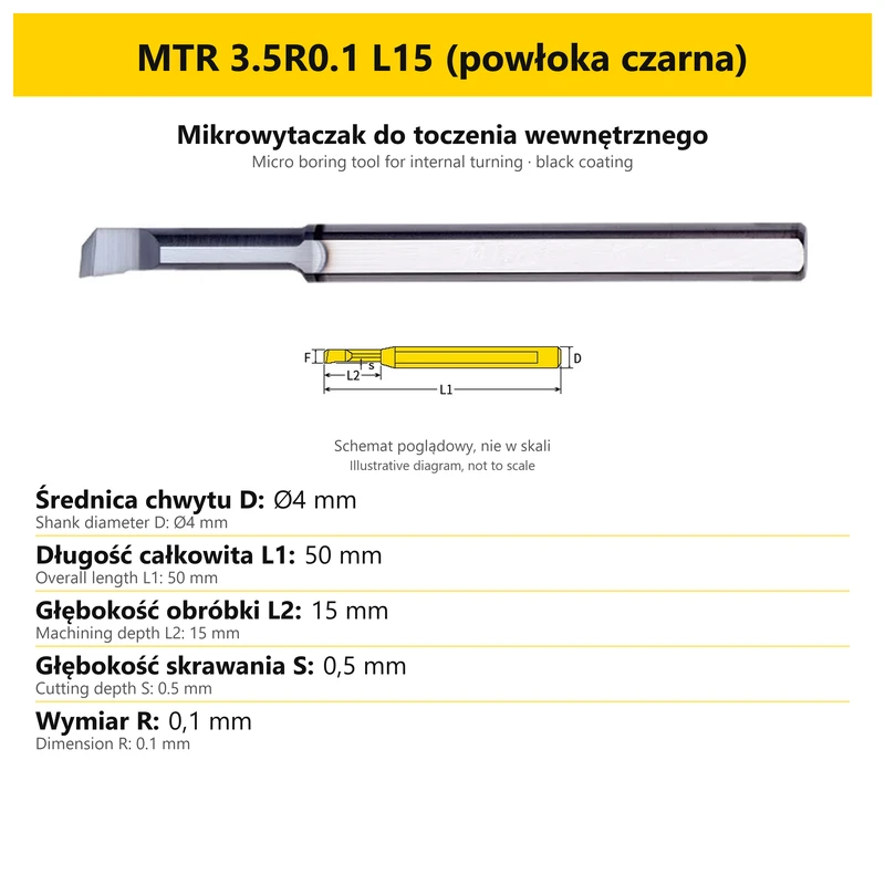
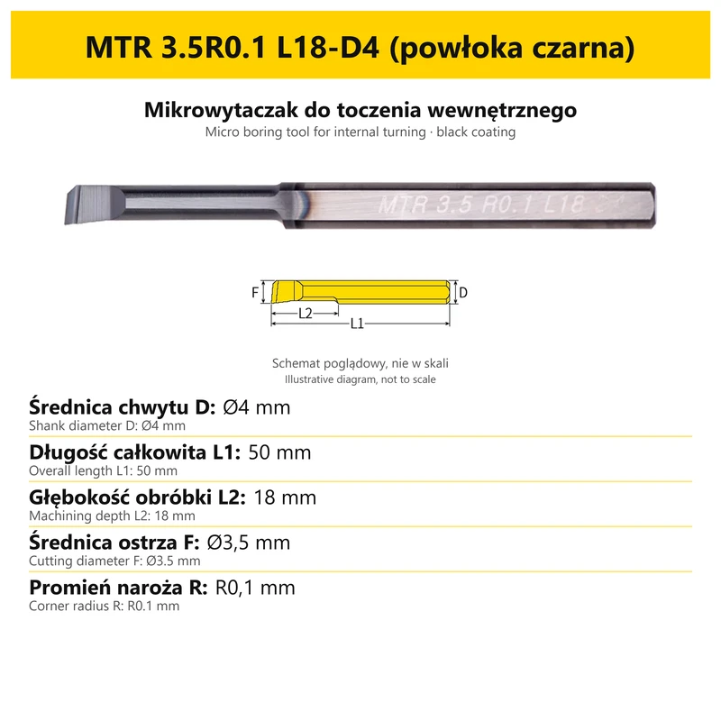
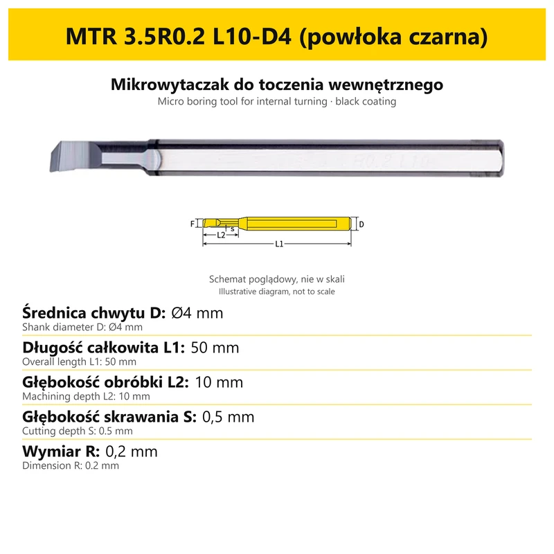
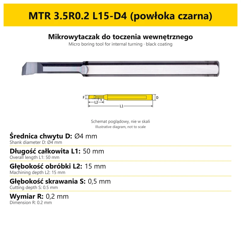
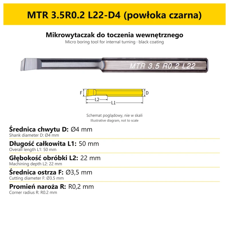
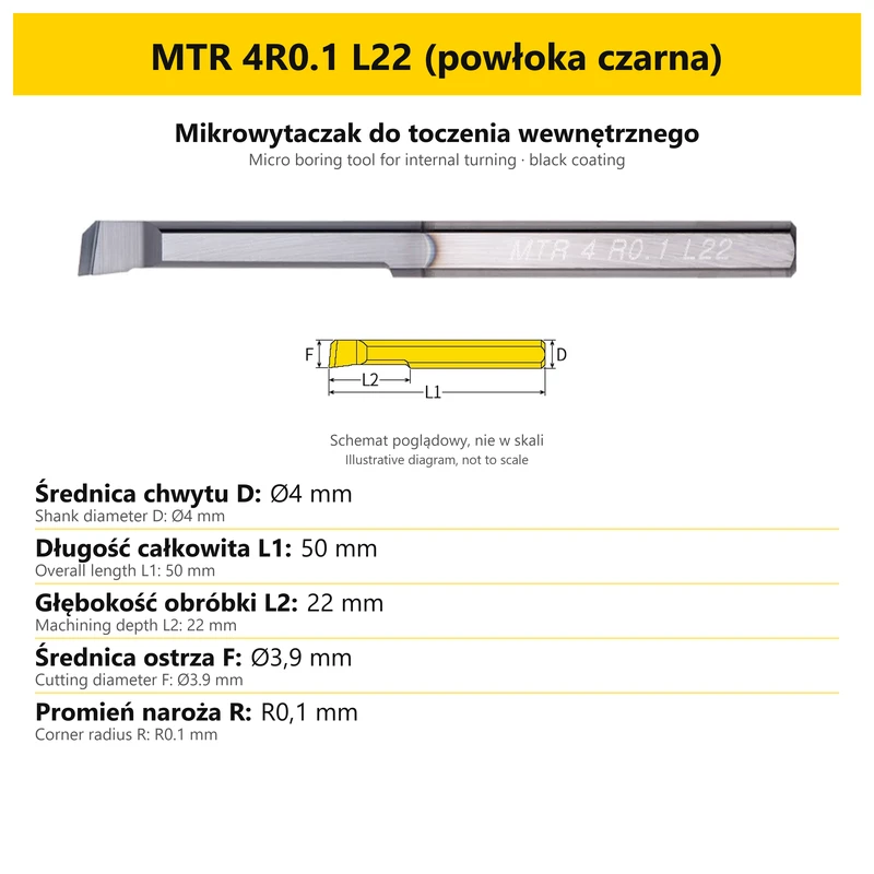
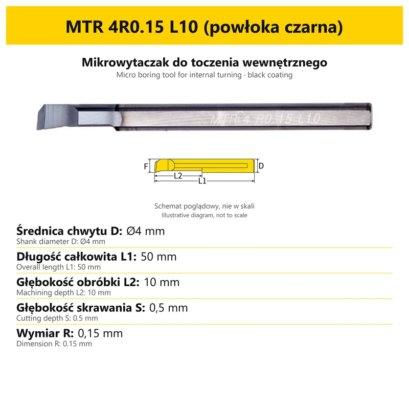
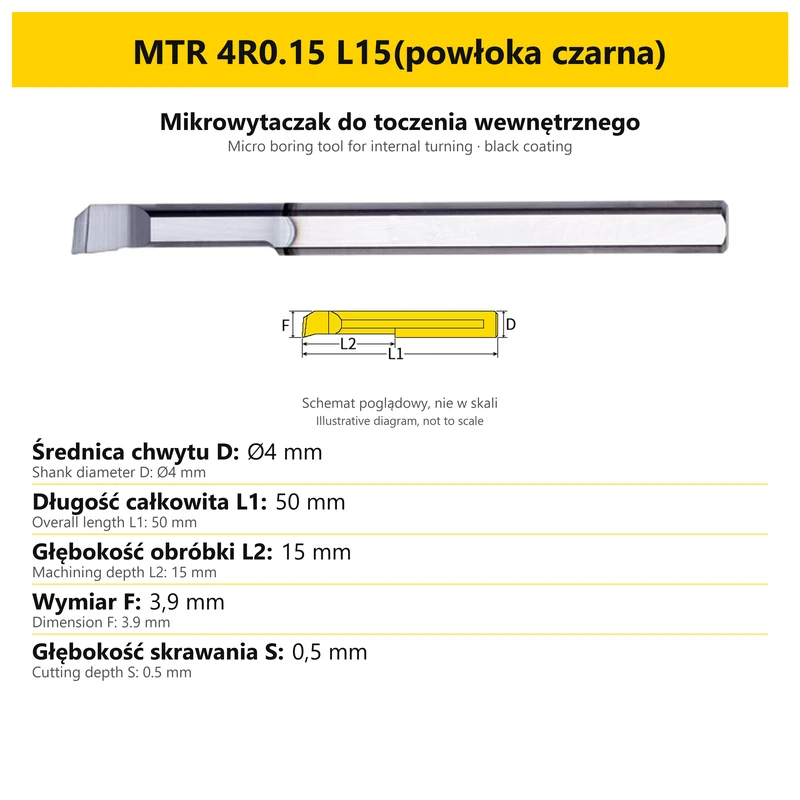
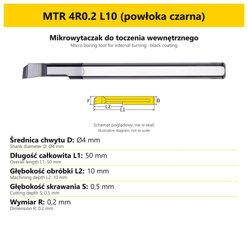
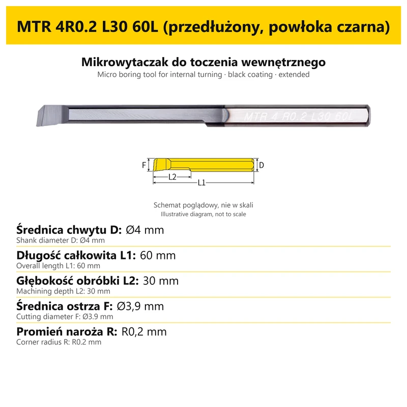
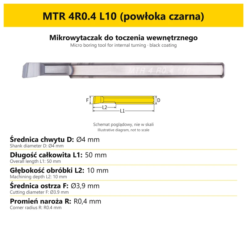
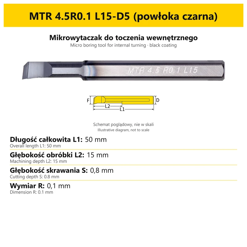
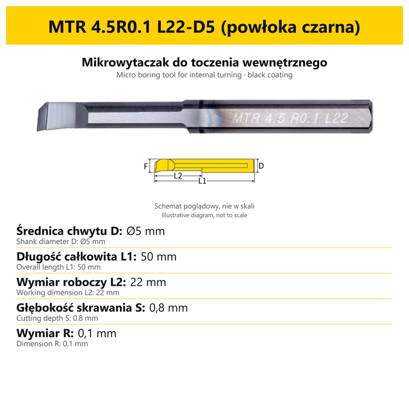
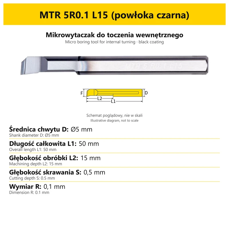
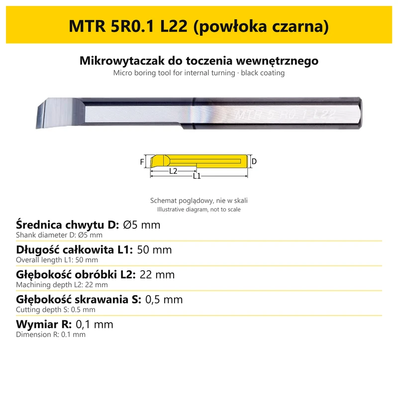
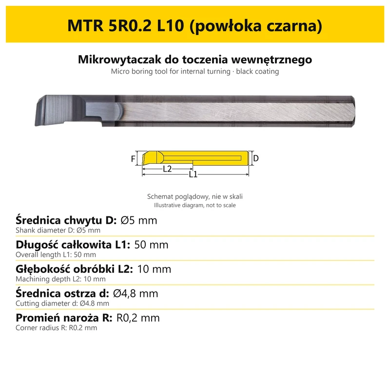
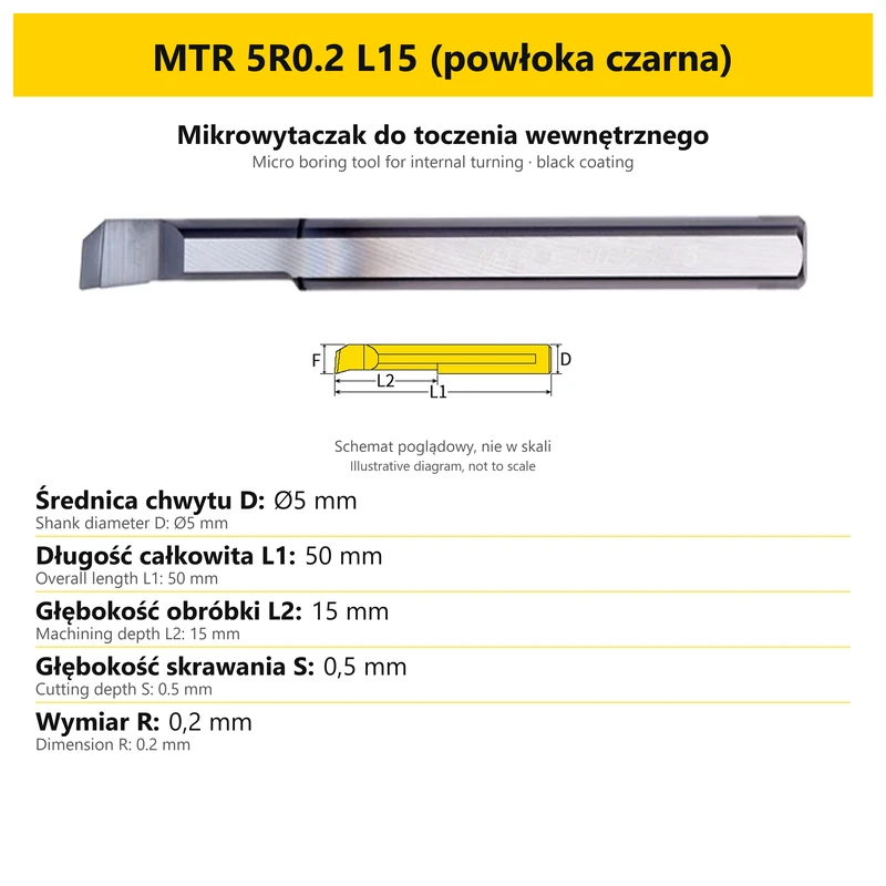
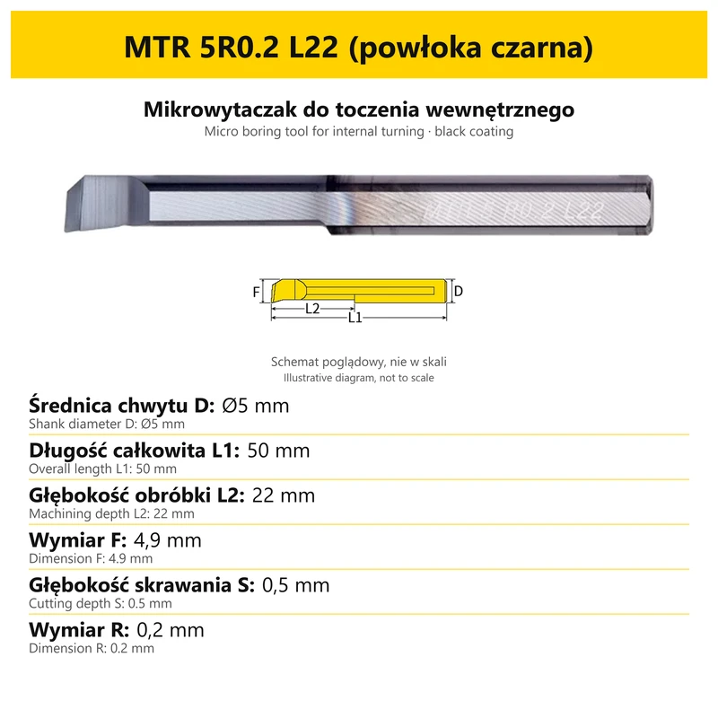
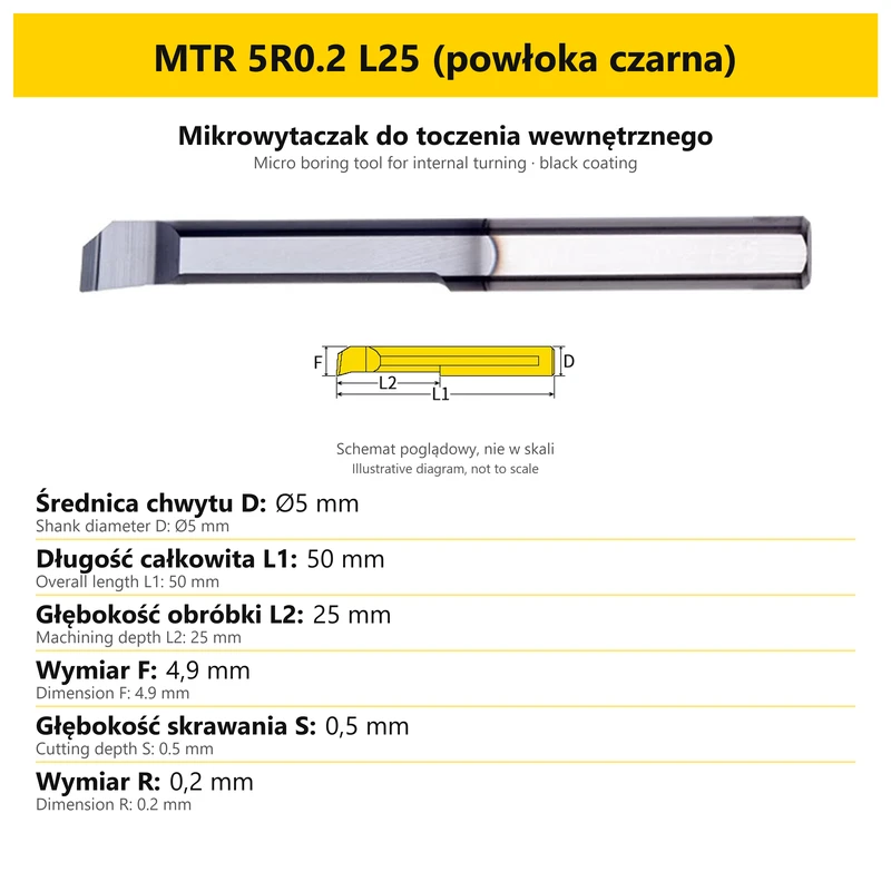
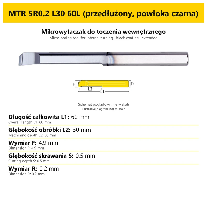
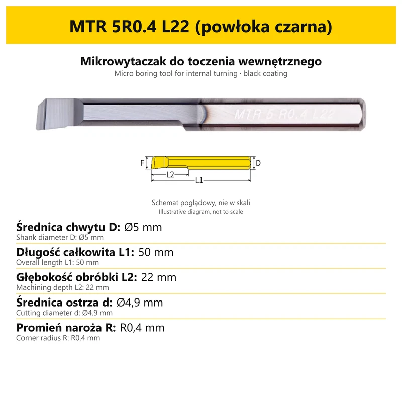
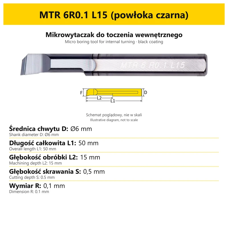
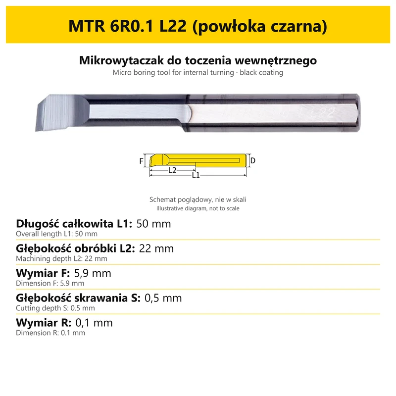
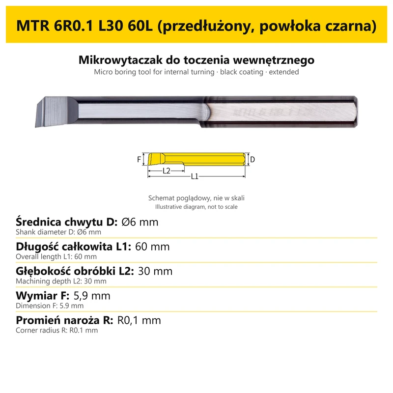
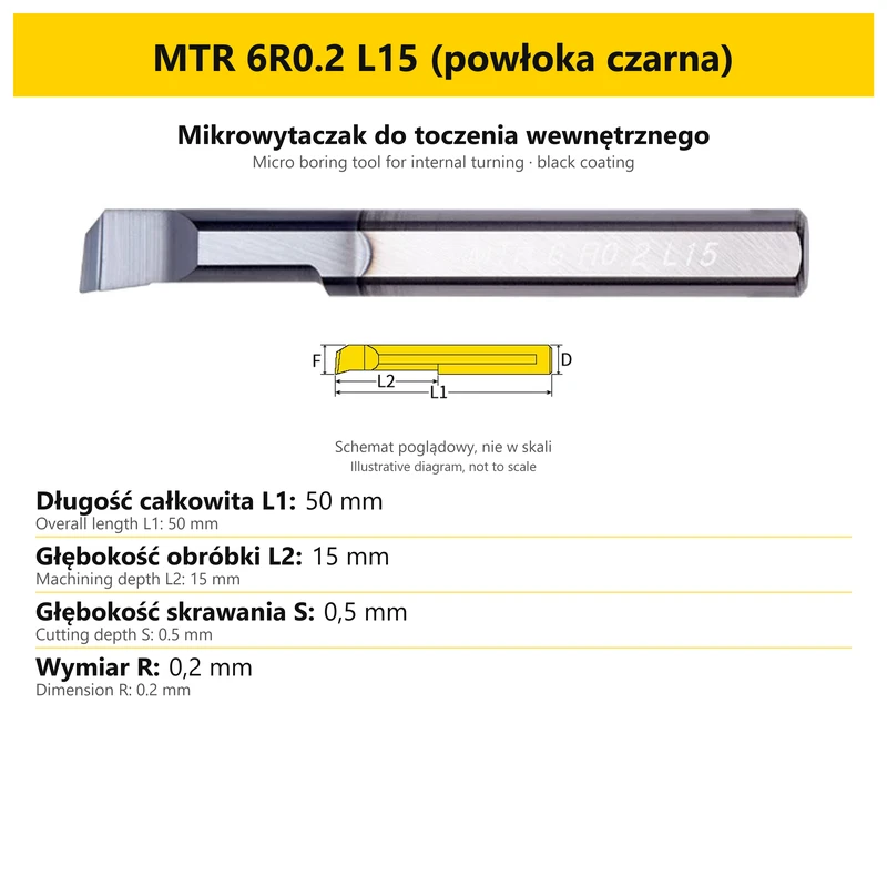
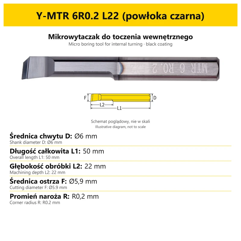
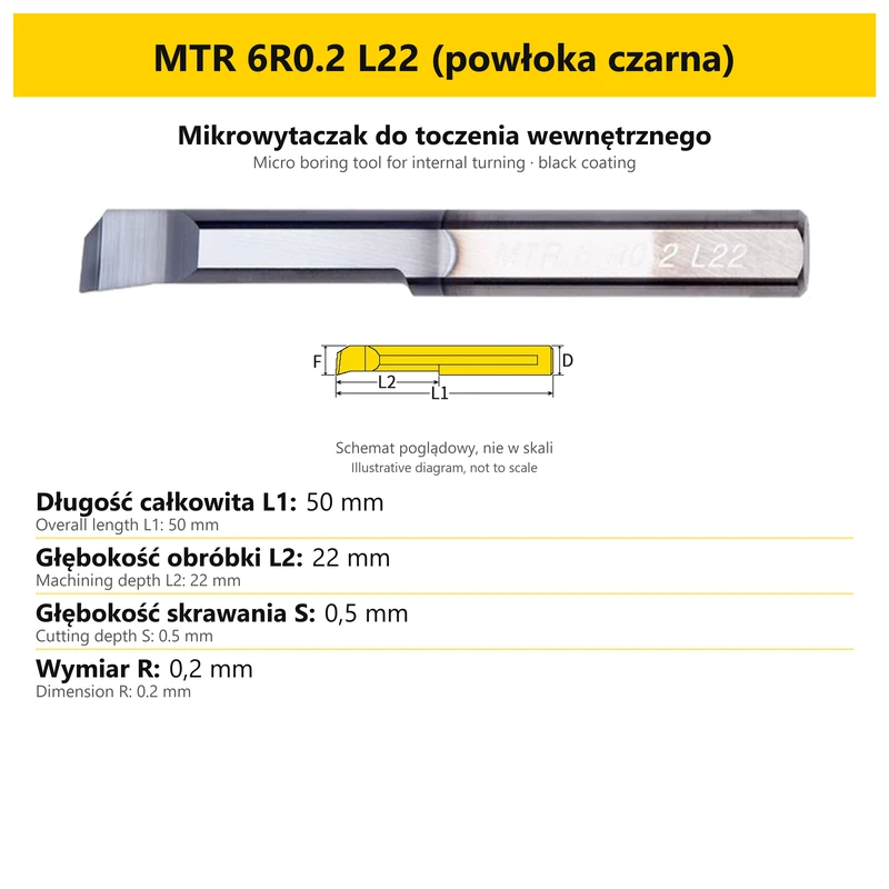
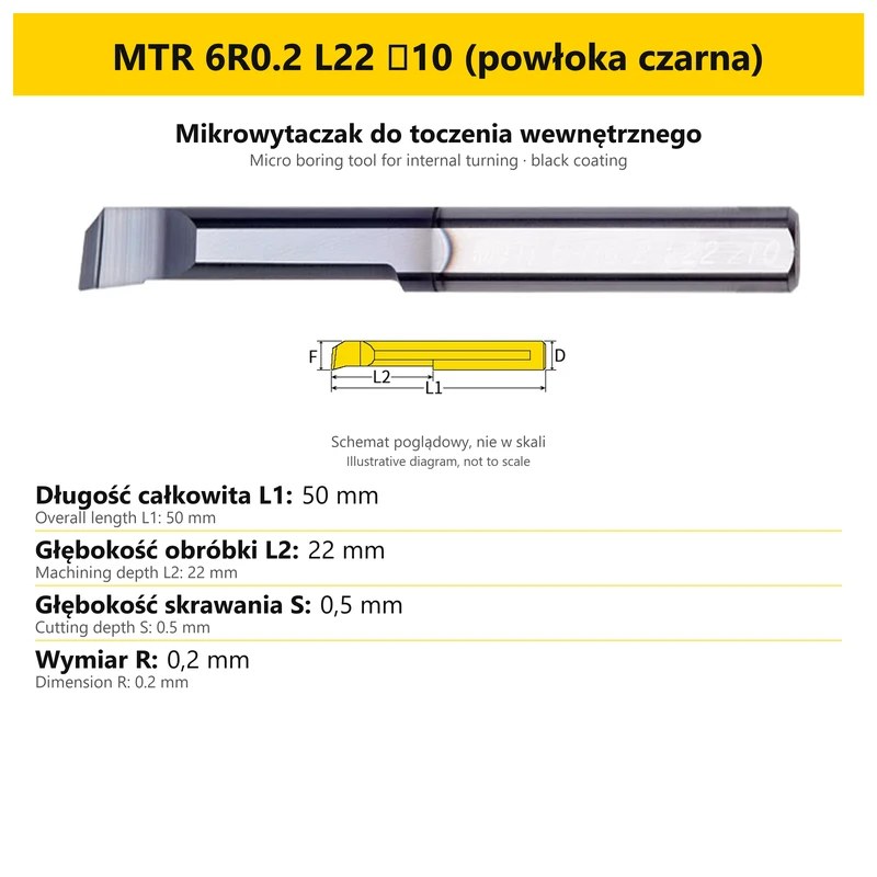
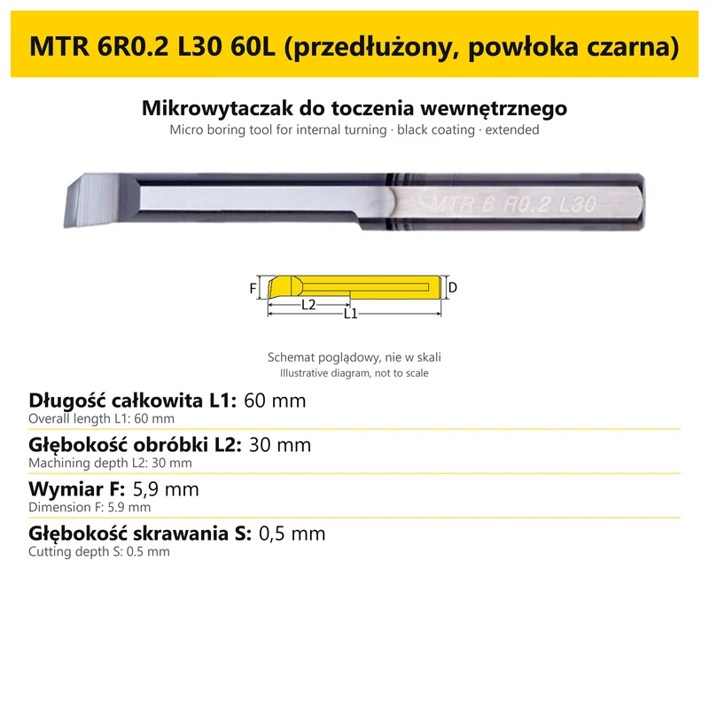
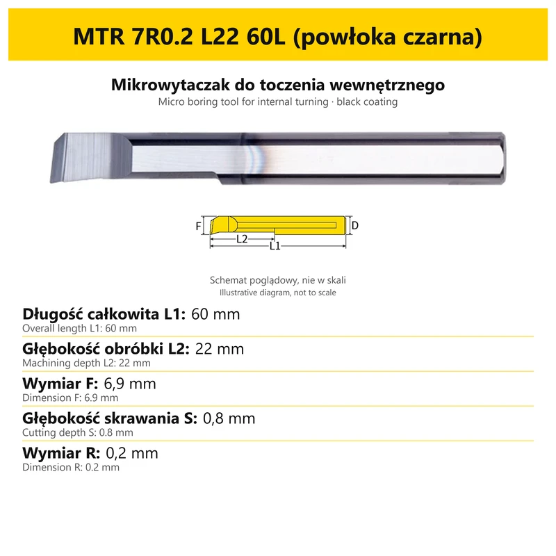
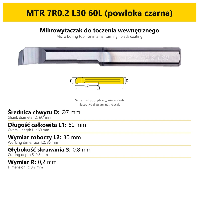
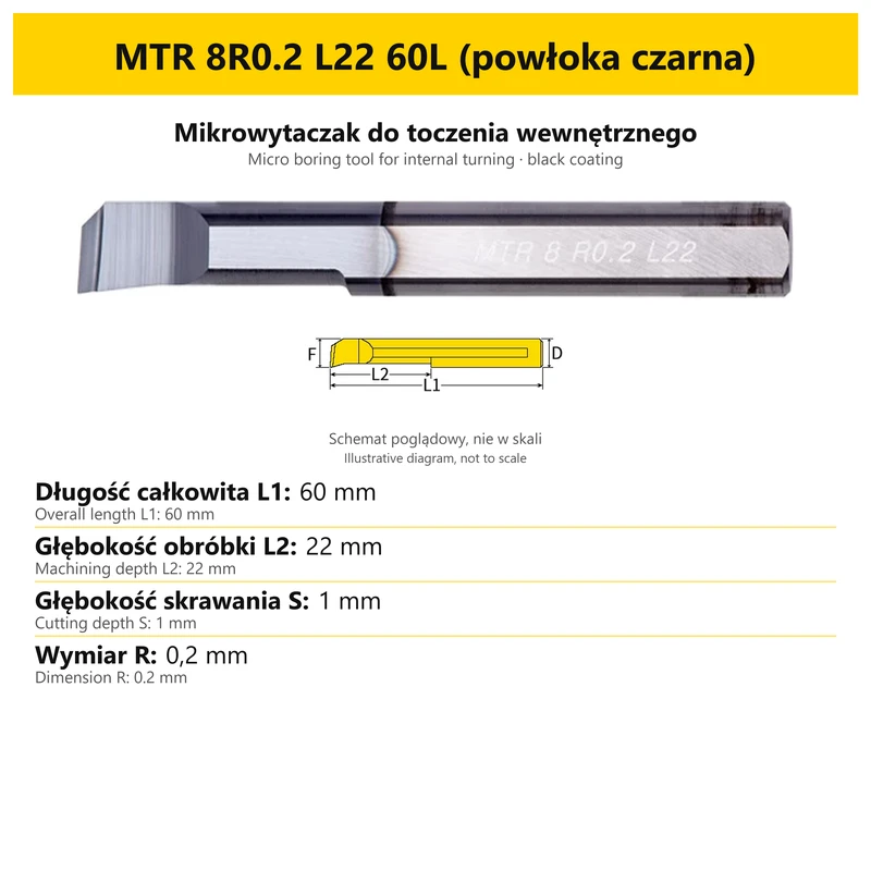
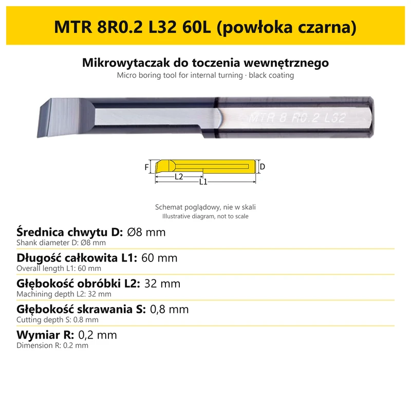
MTR is a family of solid carbide micro tools for internal turning. Version selection includes the complete option code, cutting geometry, holding dimensions and the reach required for the intended operation. Individual versions in the family can have different dimensions and different field designations in their diagrams.
Compare each option with its own card. Dimensions for one version do not automatically describe the other tools in the family.
Application
- Internal turning using the appropriate cutting portion.
- Selecting a tool for the workpiece geometry and access to the machining area.
- Comparing the selected version dimensions with the requirements of the particular workpiece.
| Machining feature | Selection factor |
|---|---|
| Machining operation | Internal turning |
| Cutting portion | Geometry and dimensions specified for the particular version |
| Machining area | Access and reach required by the chosen workpiece |
Workpiece material, tool geometry and holding arrangement affect the choice of operating conditions. The dimensional example identifies a version; it is not a cutting-speed or feed-rate chart.
Construction and specification
| Feature | Details |
|---|---|
| Tool family | MTR |
| Tool material | Solid carbide |
| Machining operation | Internal turning |
| Construction | Single-ended tool with a cutting portion and shank |
| Version selection | Complete option code in the product selector |
The complete option designation identifies the version being ordered. When comparing two tools, consider every part of the code and the corresponding dimensions. A right-hand, left-hand or double-ended version, where available in the selector, must suit the tool setup in the machine.
Dimensions of an example option
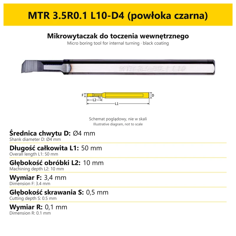
MTR 3.5R0.1 L10-D4 (powłoka czarna)
| Parameter | Value for the example |
|---|---|
| Shank diameter D | Ø4 mm |
| Overall length L1 | 50 mm |
| Machining depth L2 | 10 mm |
| Dimension F | 3.4 mm |
| Dimension R | 0.1 mm |
| Cutting depth S | 0.5 mm |
The table applies only to the illustrated option. For a different code, use the card assigned to that version.
Understanding the dimensions
Each field in the example below has its own label and value. Read the symbol together with the dimension description. Distinguish cutting-portion dimensions, holding dimensions, overall length and working reach because they serve different selection purposes. This table applies only to option MTR 3.5R0.1 L10-D4 (powłoka czarna).
| Designation / feature | Role in selection | What to check |
|---|---|---|
| L1 | Length of the complete tool | Available tool space and the holding arrangement |
| L2 | Working dimension shown on the card | Required reach for the particular operation |
| d / D / F | Different geometrical fields depending on the family | The relevant label on the selected tool card |
| Cutting portion | Separate dimensions in the example option table | Workpiece geometry and the requirements of the particular operation |
Read each dimension symbol together with its label. The same symbol can have a different meaning in another micro-tool family.
Selecting the tool for the operation
| Step | Selection | Comparison |
|---|---|---|
| 1 | Tool family and geometry | Internal turning |
| 2 | Cutting-portion dimensions | Values beside the appropriate card symbols |
| 3 | Dimension L2 | Required reach, distinguished from overall length L1 |
| 4 | Version and holding arrangement | Compatibility of the selected tool, toolholder and intended operation |
Selection should account for access to the machining area. Overall length alone does not define machining depth; the relevant working dimension and compatibility with the holding arrangement must also be considered.
Holding and using the option card
Match the tool to its holder using the holding portion and dimensions of the selected version. Check the position of the cutting portion relative to the workpiece, the working length and the space required by the rest of the tool.
The card shows the complete tool. The photograph and annotations are illustrative and are not a scale drawing. Read the numerical dimension values rather than measuring the image on screen. The option name identifies the version being ordered.
Frequently asked questions
Does L1 define machining depth?
L1 identifies the overall length. Working dimension L2 and the cutting geometry are separate information.
Does a symbol always have the same meaning?
No. Use the label for the particular family and option. Do not transfer the meaning of F or d between different tools.
Can I determine a size by measuring the photograph?
No. The photograph is illustrative. Use the stated numerical dimension values for selection.
Which version will be ordered?
The version selected in the product options. Compare its full code with the option card title and values.
Bestsellers
-
Bestseller
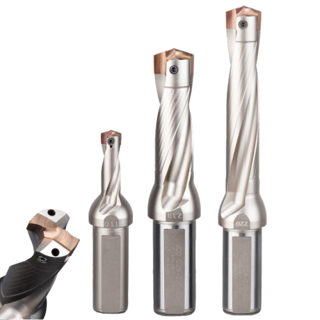
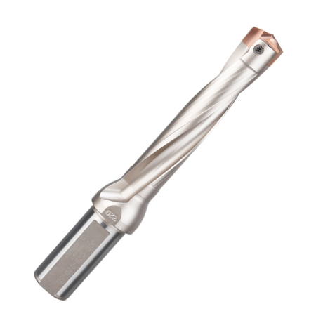
JCD modular drill with replaceable tip - internal cooling, for deep holes | GrotXD
JCD C20-100-3D Ø10~10.9 JCD C20-110-3D Ø11~11.9 JCD C20-120-3D Ø12~12.9 JCD C20-130-3D Ø13~13.9 JCD C20-140-3D Ø14~14.9 + 61 morePrice €69.52Price €56.52without VAT -
Price €17.09Price €13.90without VAT
-
Price €7.07Price €5.74without VAT
-
Price €7.52Price €6.12without VAT
-
Bestseller
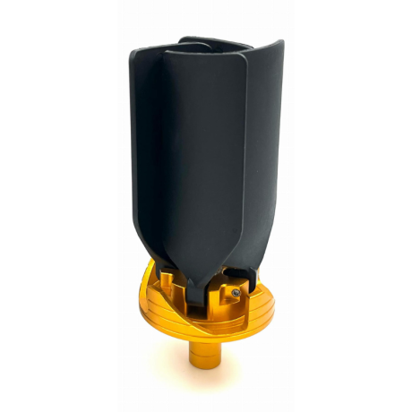
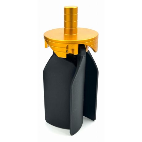 Other Accessories 0.00
CNC Chip Fan / Chip Blower
Complete CNC chip fan Kit: blades, springs, pins and screwsPrice €53.56Price €43.55without VAT -
Bestseller
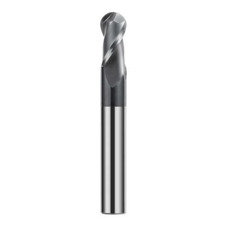
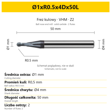 Ball Nose End Mills 0.00
2-Flute Carbide Ball Nose End Mill - HYPERCUT
Ø1xR0.5x4Dx50L Ø1.5xR0.75x4Dx50L Ø2xR1x4Dx50L Ø2.5xR1.25x4Dx50L Ø3xR1.5x3Dx50L + 26 morePrice €10.09Price €8.21without VAT -
Bestseller
 2-Flute End Mills 0.00
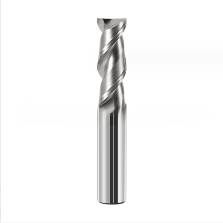
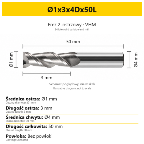
2-Flute Carbide End Mill for Aluminium
Ø1x3x4Dx50L Ø1.5x4x4Dx50L Ø2x6x4Dx50L Ø2.5x7.5x4Dx50L Ø3x9x3Dx50L + 31 morePrice €5.33Price €4.33without VAT -
Bestseller
 2-Flute End Mills 0.00
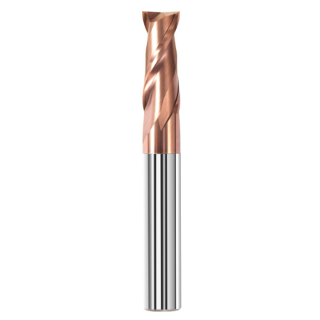
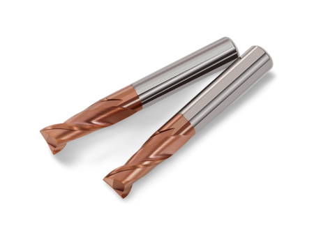
2-Flute Carbide End Mill for Steel 55 HRC - TiSiN - Solid Carbide
Ø6x24x6Dx75L Ø8x25x8Dx75L Ø4x20x4Dx100L Ø5x30x5Dx100L Ø6x30x6Dx100L + 31 morePrice €4.38Price €3.56without VAT -
Bestseller
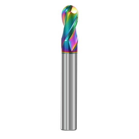
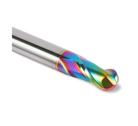 Ball Nose End Mills 0.00
2-Flute DLC Coated Carbide Ball Nose End Mill| DuraEdge Alu
Ø1.0xR0.5x4Dx50L Ø1.5xR0.75x4Dx50L Ø2.0xR1x4Dx50L Ø2.5xR1.25x4Dx50L Ø3.0xR1.5x3Dx50L + 34 morePrice €7.85Price €6.38without VAT -
Bestseller
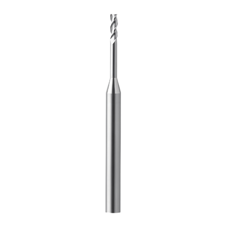
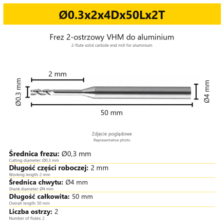 2-Flute End Mills 0.00
2-Flute End Mill for Aluminium | VHM | Miniature Ø0.3 - Ø0.9
Ø0.3x2x4Dx50Lx2T Ø0.3x3x4Dx50Lx2T Ø0.3x4x4Dx50Lx2T Ø0.4x2x4Dx50Lx2T Ø0.4x3x4Dx50Lx2T + 28 morePrice €7.95Price €6.47without VAT -
Bestseller
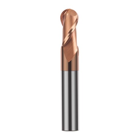
 Ball Nose End Mills 0.00
2-Flute TiSiN Coated Carbide Ball Nose End Mill
Ø1xR0.5x4Dx50L Ø1.5xR0.75x4Dx50L Ø2xR1x4Dx50L Ø2.5xR1.25x4Dx50L Ø3xR1.5x3Dx50L + 38 morePrice €7.24Price €5.89without VAT -
Bestseller
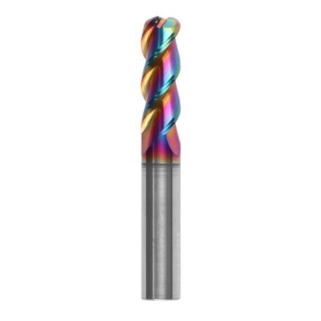
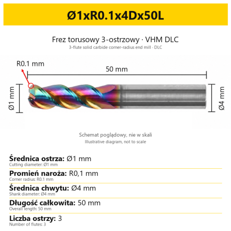
3-Flute Carbide Corner Radius End Mill for Aluminium| AL DLC
Ø1xR0.1x4Dx50L Ø1xR0.2x4Dx50L Ø1xR0.3x4Dx50L Ø1.5xR0.1x4Dx50L Ø1.5xR0.2x4Dx50L + 137 morePrice €5.89Price €4.79without VAT -
Bestseller
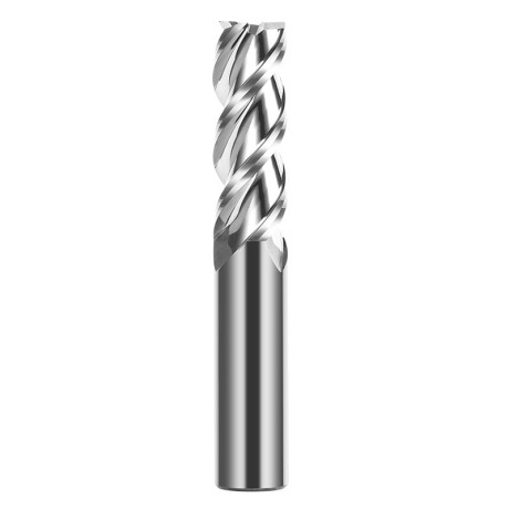
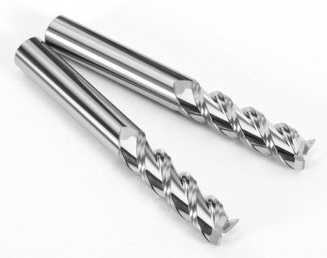 3-Flute End Mills 0.00
3-Flute Carbide End Mill VHM Z-3 for Aluminium| TriMill AL
Ø1x3xD4x50L Ø1.5x5x4Dx50L Ø2x6x4Dx50L Ø2.5x8x4Dx50L Ø3x9x3Dx50L + 41 morePrice €5.08Price €4.13without VAT -
Bestseller
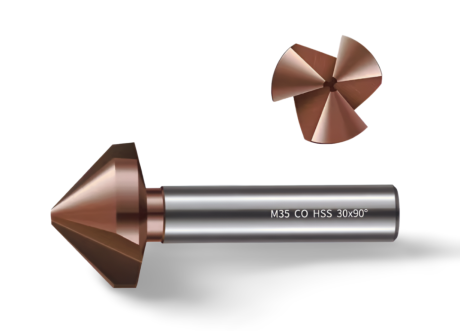
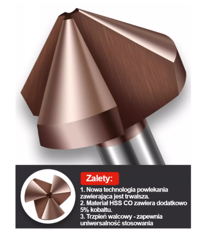 Countersinks 0.00
3-Flute Countersink Fi4.5-fi60, 90° - HSS-CO - 5% Kobaltu | Straight Shank
Ø4.5 x 4 x 90° x 40L Ø5 x 5 x 90° x 45L Ø6.3 x 5 x 90° x 45L Ø8.3 x 6 x 90° x 50L Ø10.4 x 6 x 90° x 50L + 12 morePrice €4.79Price €3.89without VAT -
Bestseller
 3-Flute End Mills 0.00
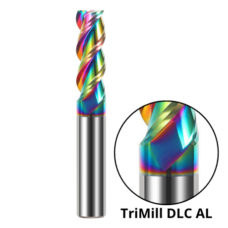
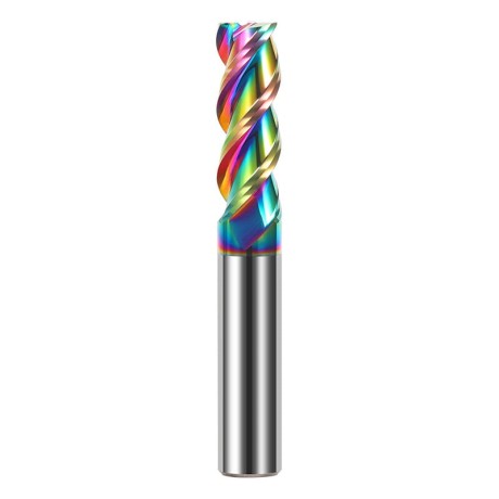
3-Flute DLC Coated Carbide End Mill | TriMill DLC AL
Ø1x3x4Dx50L Ø1.5x5x4Dx50L Ø2x6x4Dx50L Ø2.5x8x4Dx50L Ø3x8x3Dx50L + 38 morePrice €5.05Price €4.10without VAT -
Bestseller

 3-Flute End Mills 0.00
3-Flute HRC65 DLC Coated Carbide End Mill, U-Shaped Flute, for Aluminium | DuraEdge3 Alu
Ø1x3x4Dx50L Ø1.5x5x4Dx50L Ø2x6x4Dx50L Ø2.5x8x4Dx50L Ø3x9x3Dx50L + 40 morePrice €6.73Price €5.47without VAT