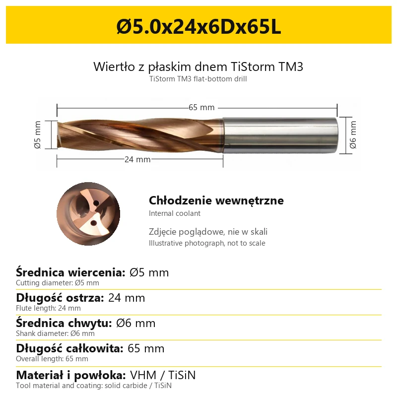
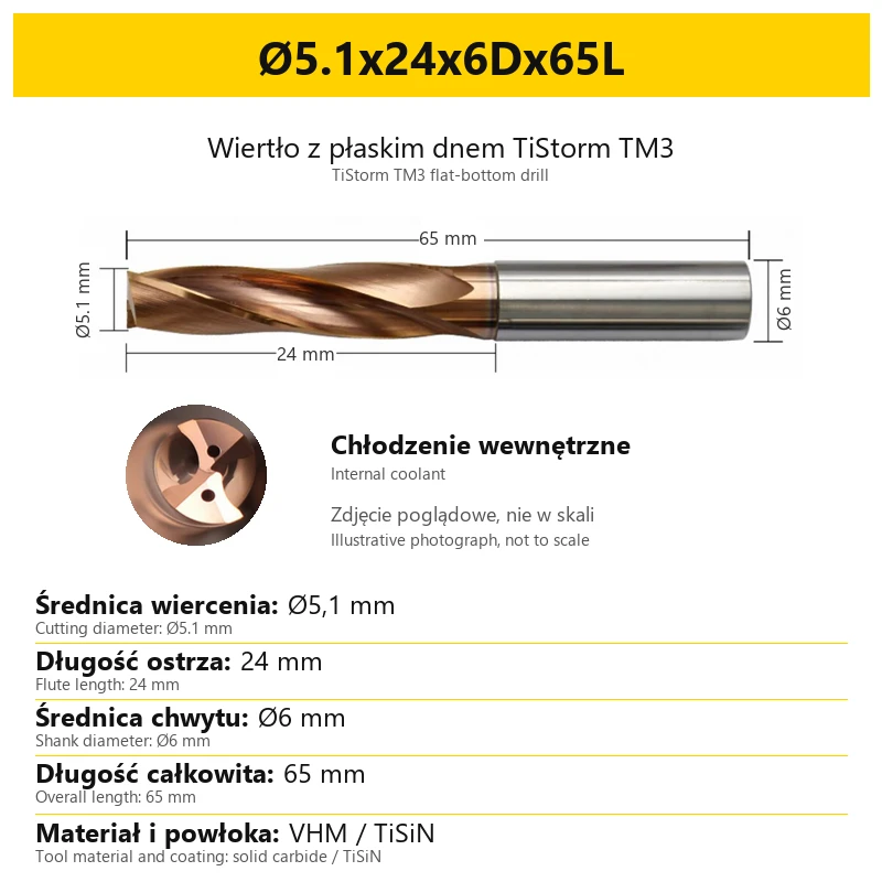
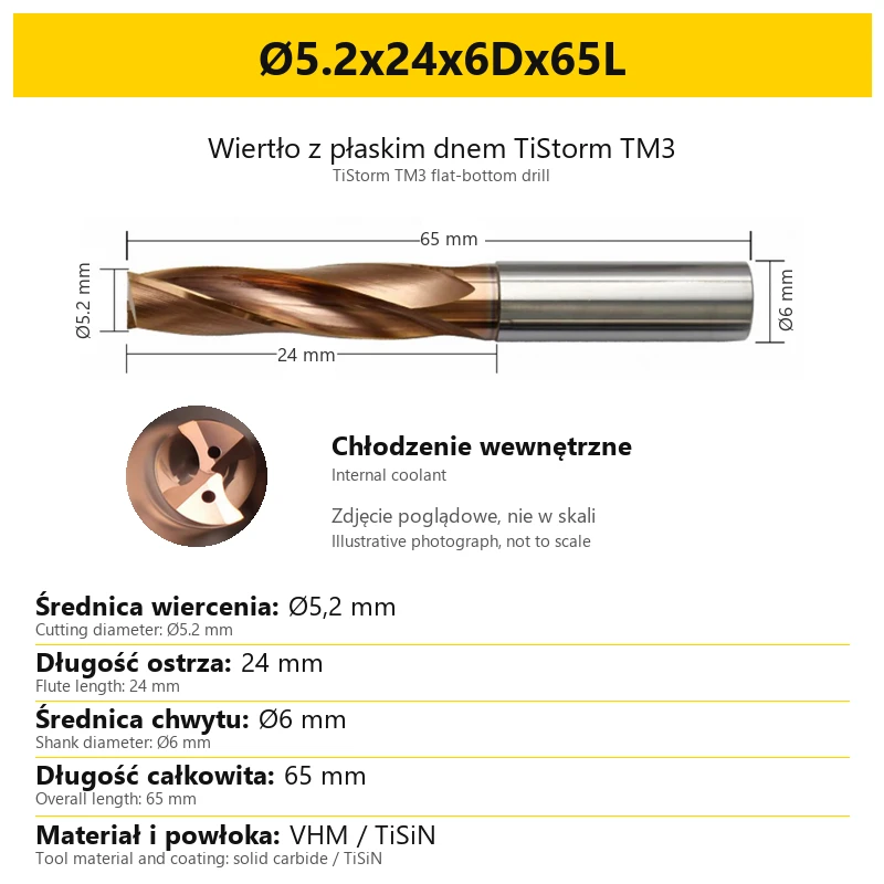
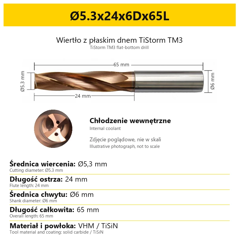
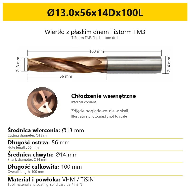
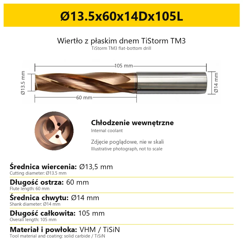
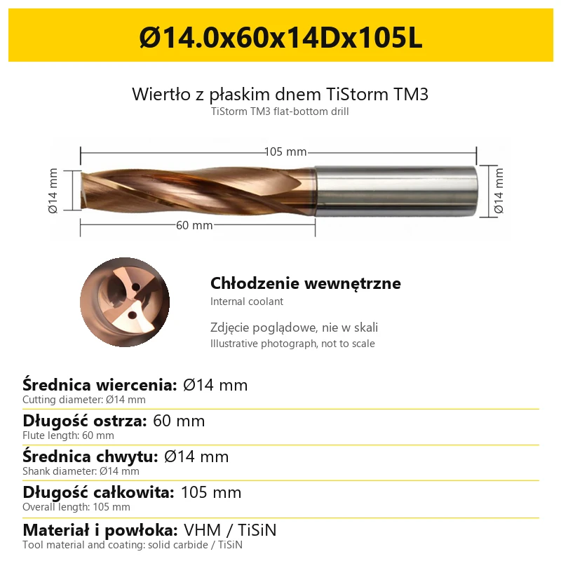


Flat Bottom Carbide Drill with Internal Coolant VHM 55HRC TiSiN TiStorm TM3
Shipping costs are not included in the price.
Shipping costs are not included in the price.

Weekly deals
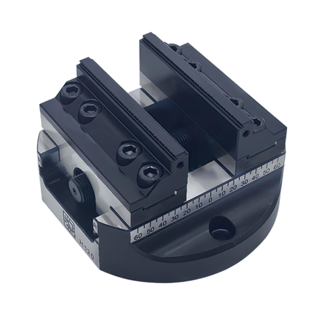
5-axis vise with hard jaws
Self-centering machine vise. Hard jaws included.
excl. VAT
Regular price:
Lowest price in the 30 days before the reduction:
Time left
Offer ends 06.11.2026 23:59. Offer applies to the vise + hard jaws bundle only.
Ask about the product

The administrator of personal data is Kortools. We process it to respond to your inquiry. More information regarding the processing of personal data can be found in privacy policy.
Select a product variant:
Individual variants may differ in price
Product code: BF6C-16647
Product description
TiStorm TM3 — solid carbide flat-bottom drill
Solid carbide · TiSiN · internal coolant · workpiece hardness up to 55 HRC
TiStorm TM3 is a solid carbide drill with a flat point and internal coolant channels. It is intended for drilling and axial counterboring, including entry or exit through inclined or curved surfaces. Select the size by cutting diameter, flute length, shank diameter and overall length.
1. Construction and technical specifications
The tool has a solid carbide body, a TiSiN coating and a cylindrical shank. Its flat point with a nominal included angle of 180° distinguishes it from a conventional pointed drill. Coolant outlets are located at the cutting end.
| Specification | Design |
|---|---|
| Tool type | Solid carbide flat-bottom drill, TiStorm TM3 series |
| Tool substrate | Solid carbide — VHM |
| Coating | TiSiN |
| Point geometry | Nominal 180° included angle; designed to produce a substantially flat hole bottom |
| Shank | Cylindrical; diameter specified separately for the selected size |
| Coolant supply | Internal — through channels in the tool |
| Workpiece hardness | Up to 55 HRC |
The 55 HRC figure refers to the hardness range of the workpiece. It is neither the hardness of the carbide tool itself nor the coating thickness. VHM and TiSiN identify the tool substrate and coating respectively.
2. Workpiece materials
Applications cover steels, including alloy and tool steels, stainless steel, cast iron and aluminium. Selection for a specific job takes account of the workpiece grade and hardness, the hole geometry and the coolant supply.
| Workpiece group | Application |
|---|---|
| Steel | Drilling and axial counterboring |
| Alloy and tool steels | Drilling and hole-bottom machining within the hardness range up to 55 HRC |
| Stainless steel | Drilling and axial counterboring |
| Cast iron | Producing holes and counterbores |
| Aluminium | Producing holes and counterbores |
These applications do not imply common spindle speeds and feed rates across the entire series. Cutting data must be selected for the diameter, workpiece grade and operating conditions.
3. Flat point and applications
The point geometry is designed to produce holes and counterbores with a substantially flat bottom. A slight concavity may remain due to the cutting-edge geometry; the term “flat bottom” does not specify a flatness tolerance.
| Operation | Example application |
|---|---|
| Entry through an inclined or curved surface | Drilling a workpiece with a non-flat entry surface |
| Exit through an inclined or curved surface | Through holes emerging on a non-flat surface |
| Axial counterboring | Producing counterbores, including locations with restricted access and curved surfaces |
| Cross holes and thin sheet | Drilling through an existing transverse hole or through a thin wall |
| Guide holes and correction of eccentric holes | Axial operations using an appropriate machining process |
| Partially open holes | Drilling near a workpiece edge where part of the hole circumference remains open |
For non-flat surfaces, the recommended range is up to three cutting diameters (3D). This is an application guideline, not a common flute length for every size. Check the selected variant for its exact dimensions.
The tool operates with an axial feed. It is not intended for side milling or cutting with a transverse feed. Suitability for thin walls or intersecting holes does not guarantee a completely burr-free result.
4. Internal coolant
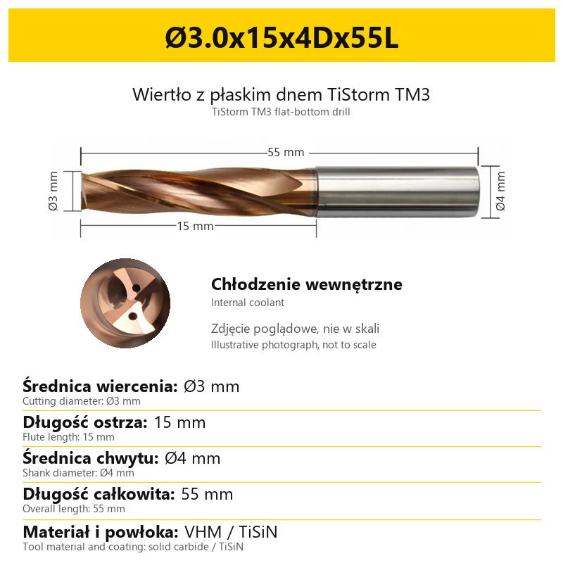
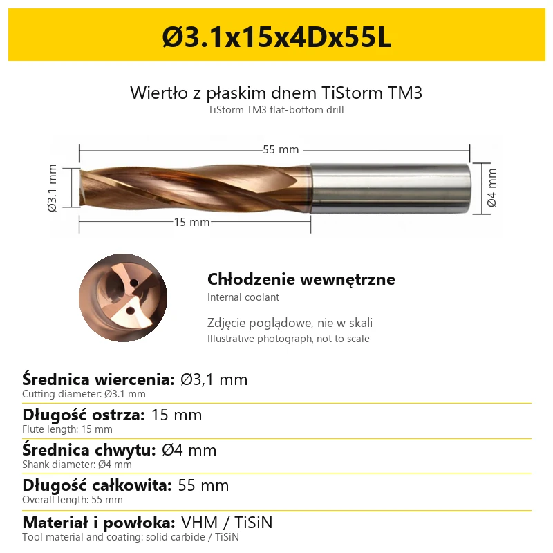
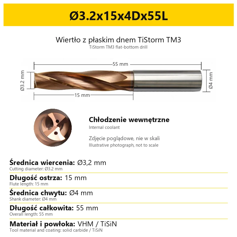
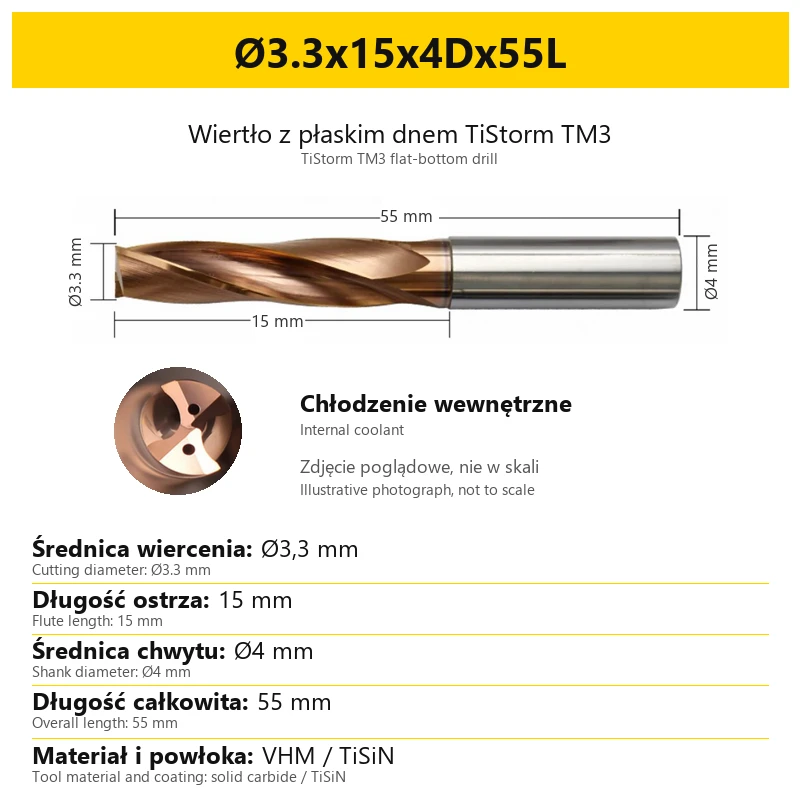
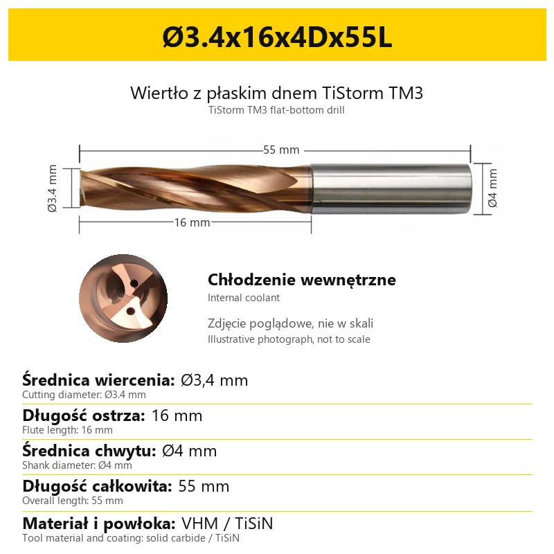
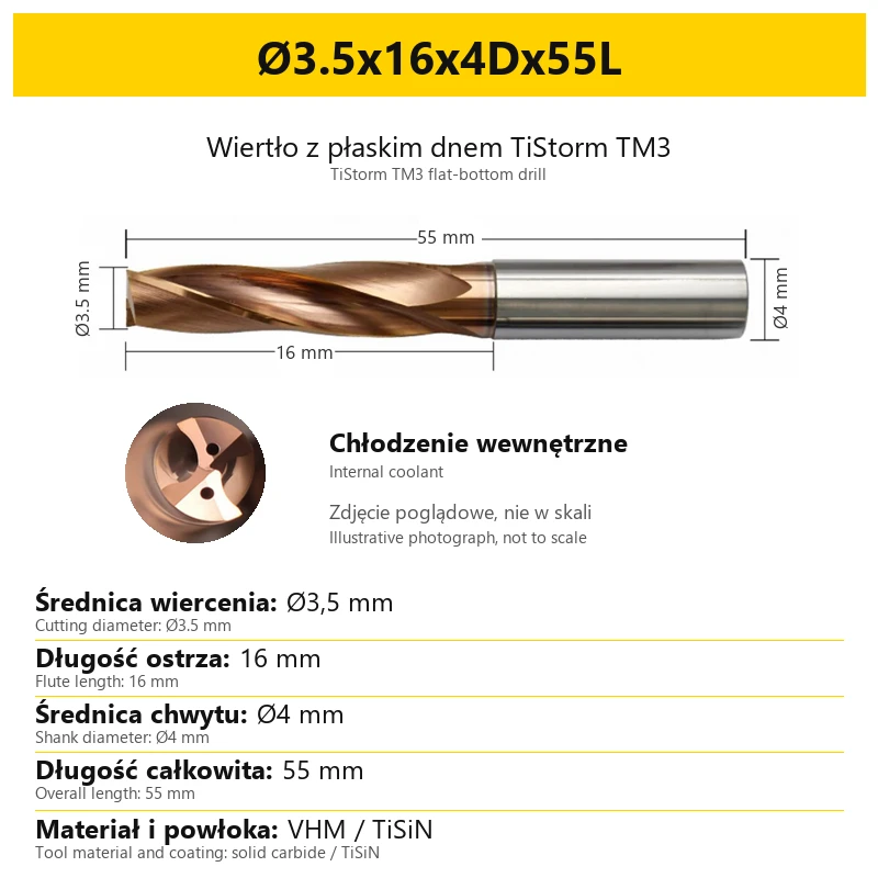
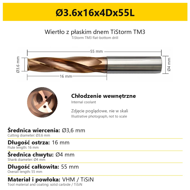
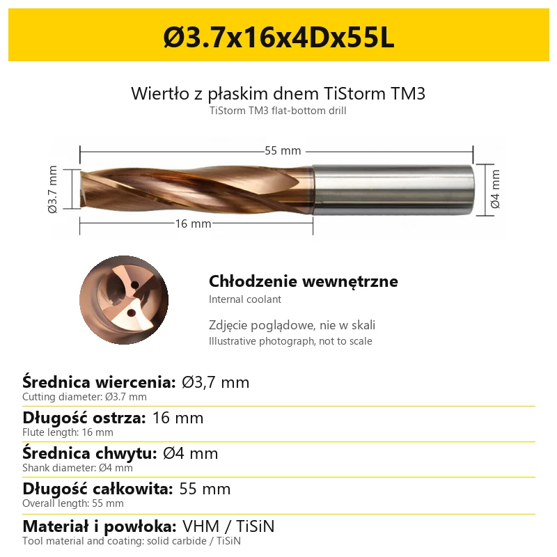
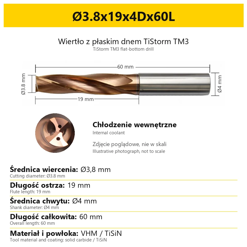
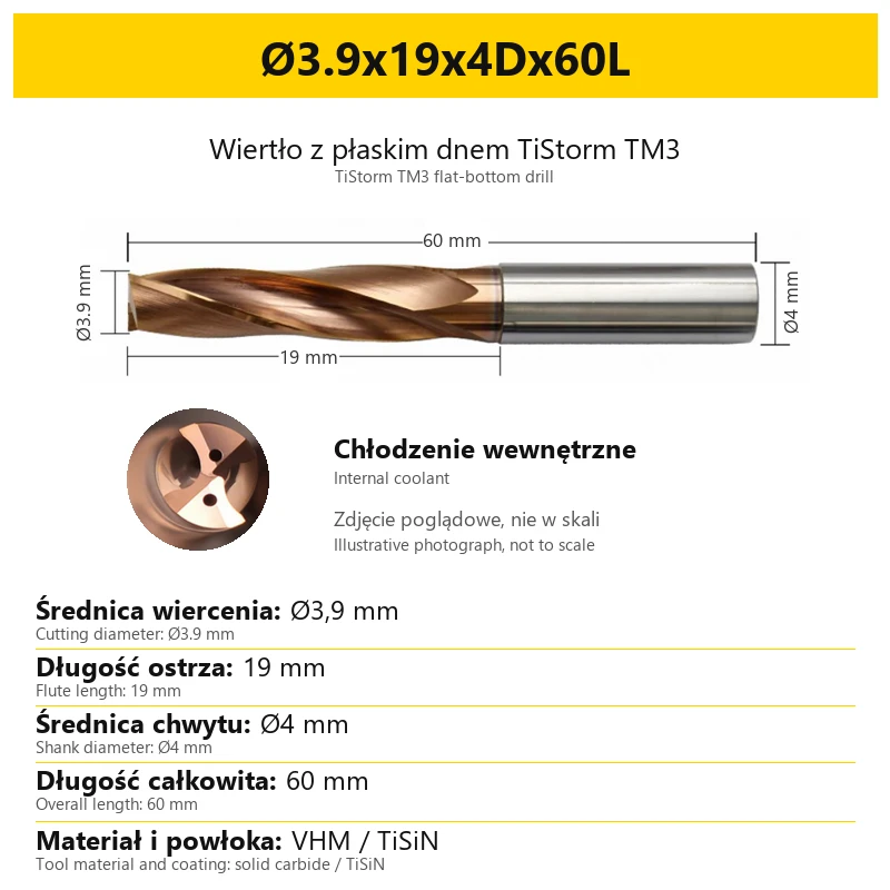
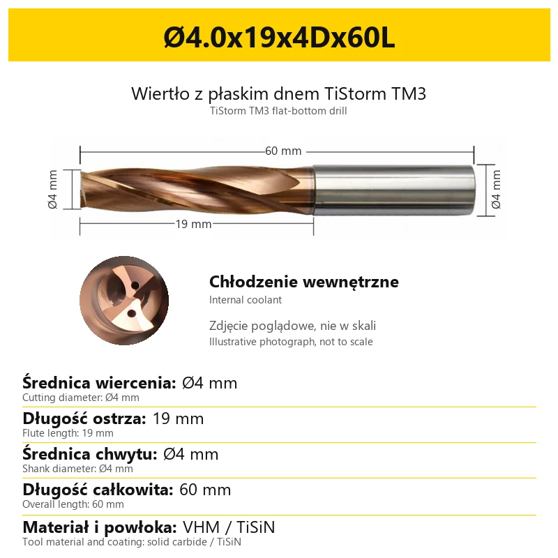
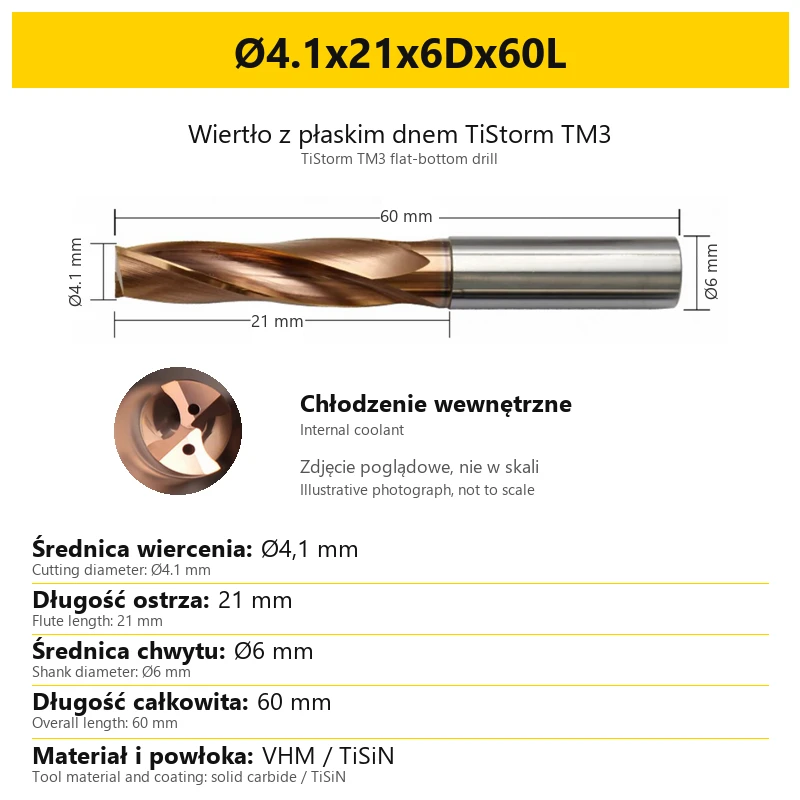
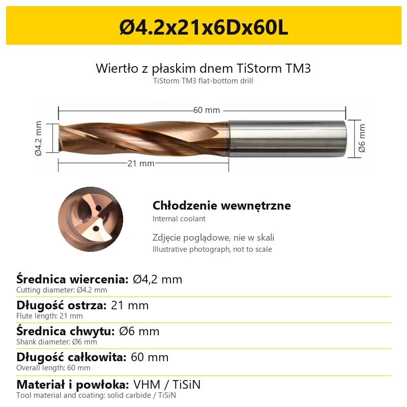
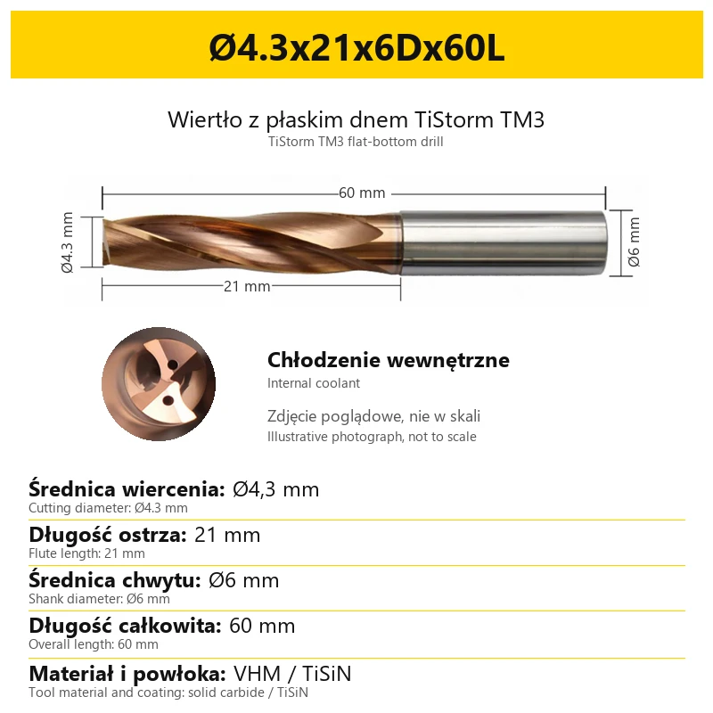
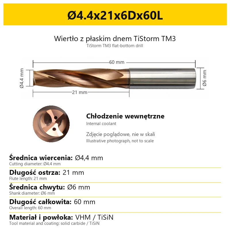
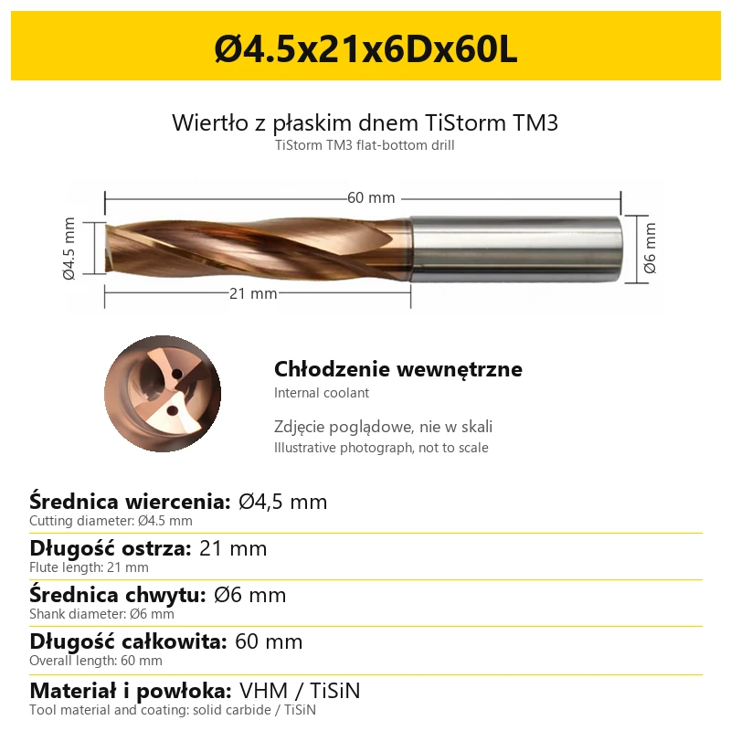
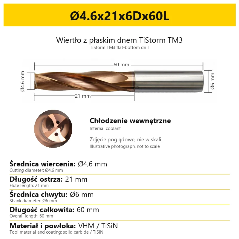
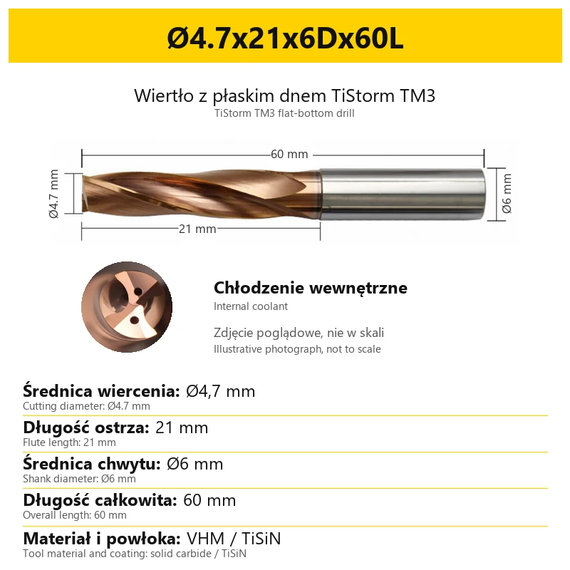
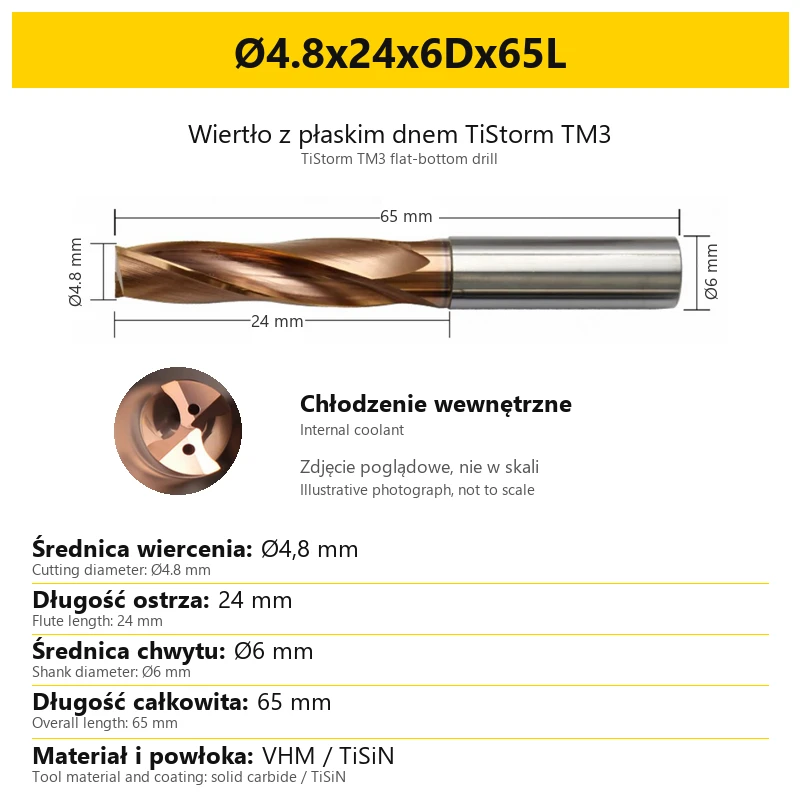
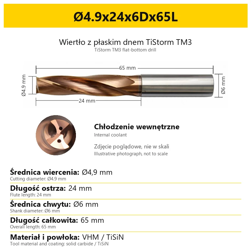
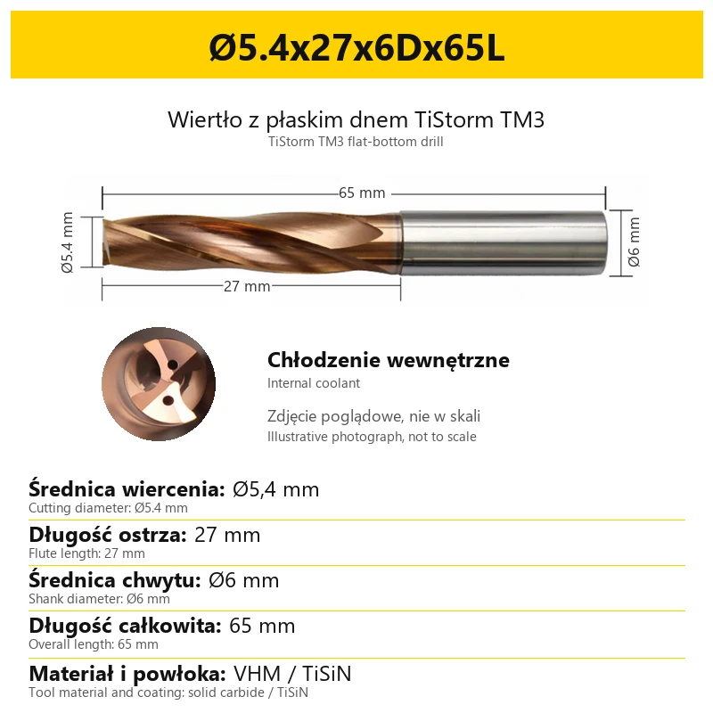
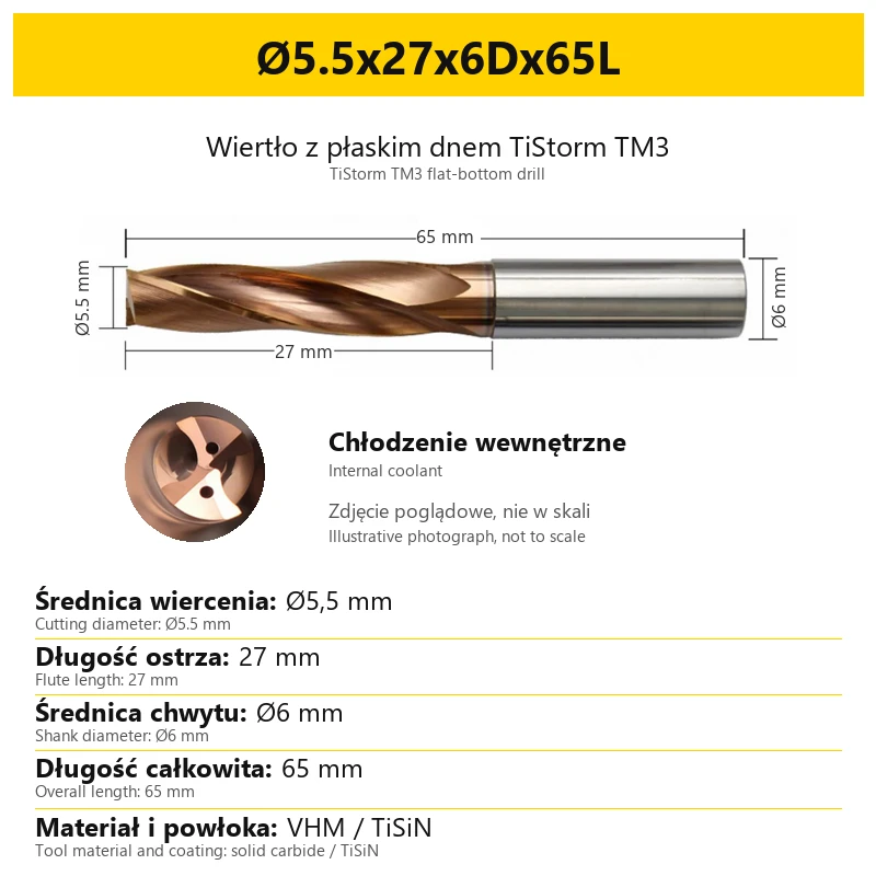
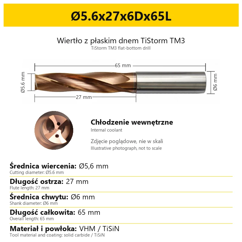
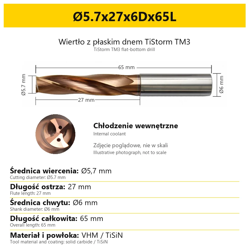
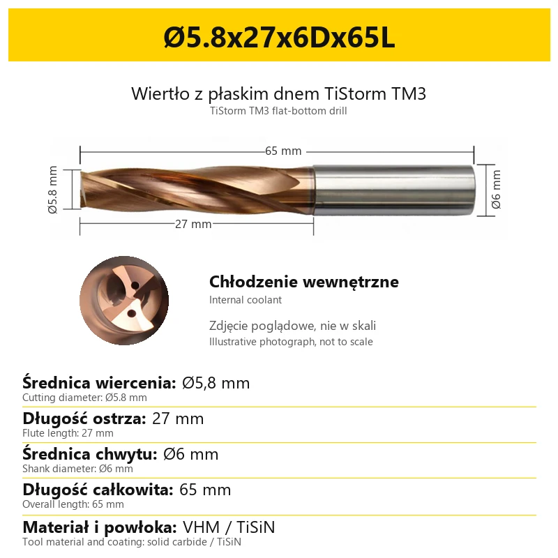
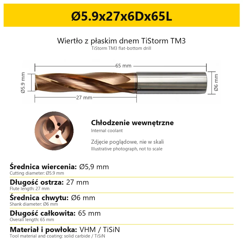
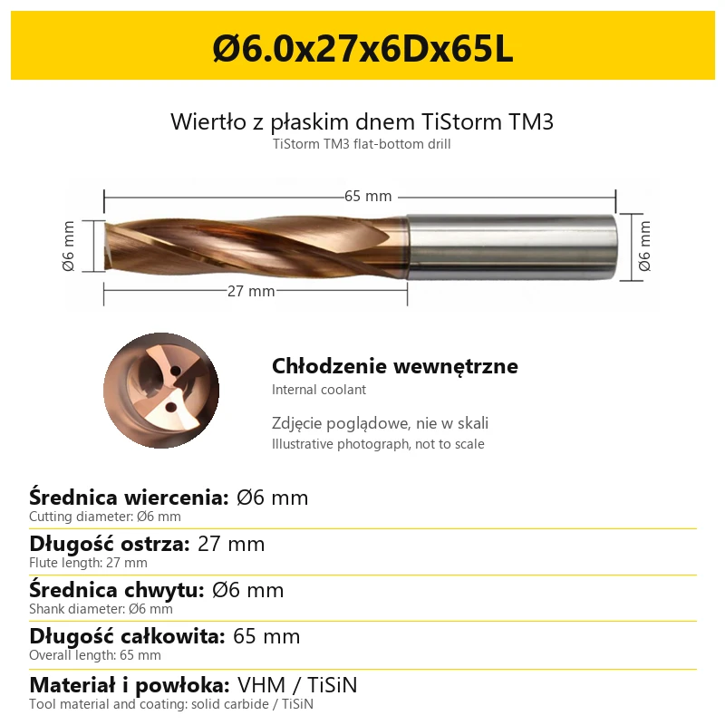
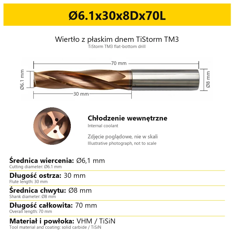
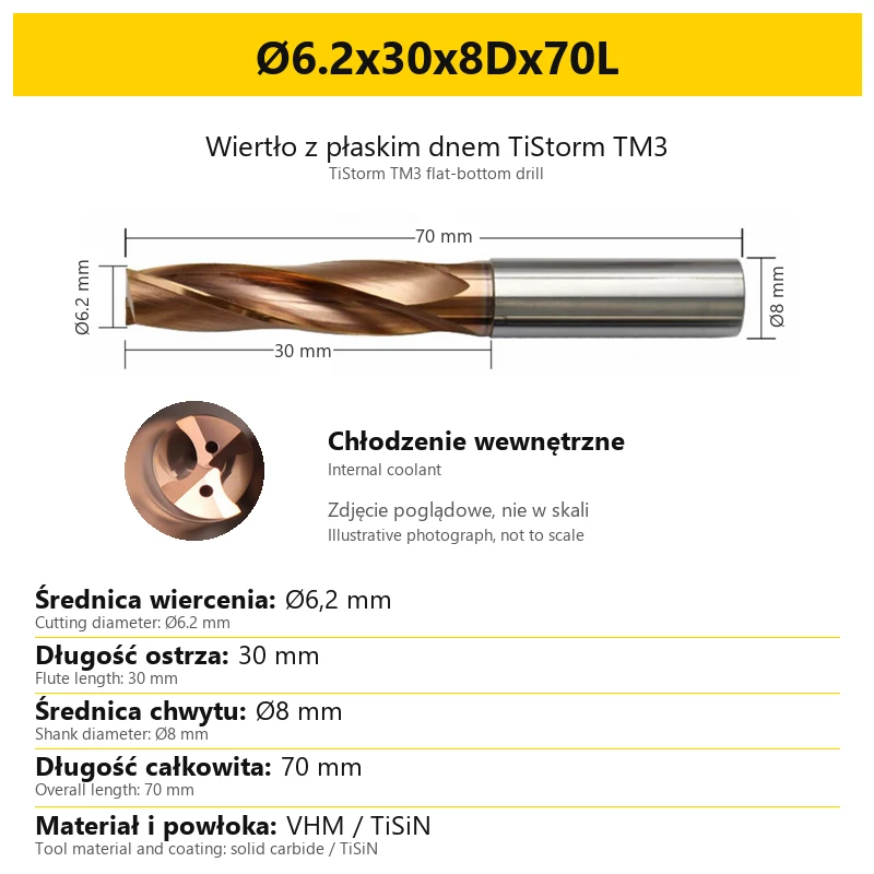
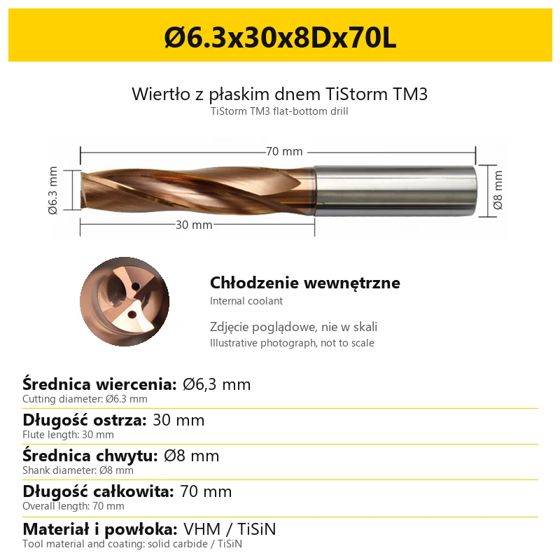
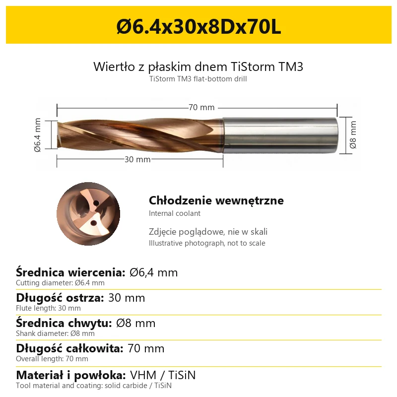
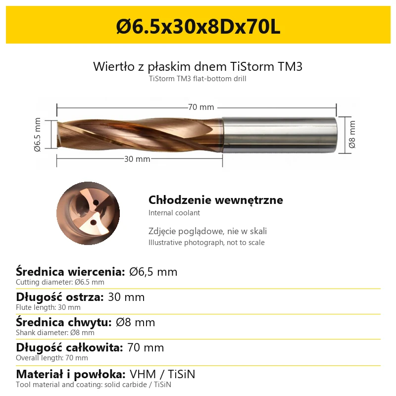
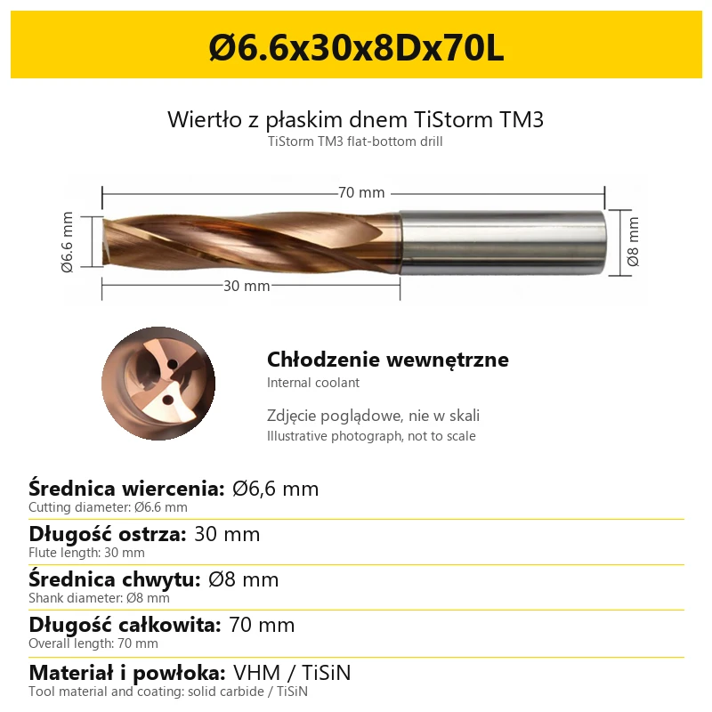
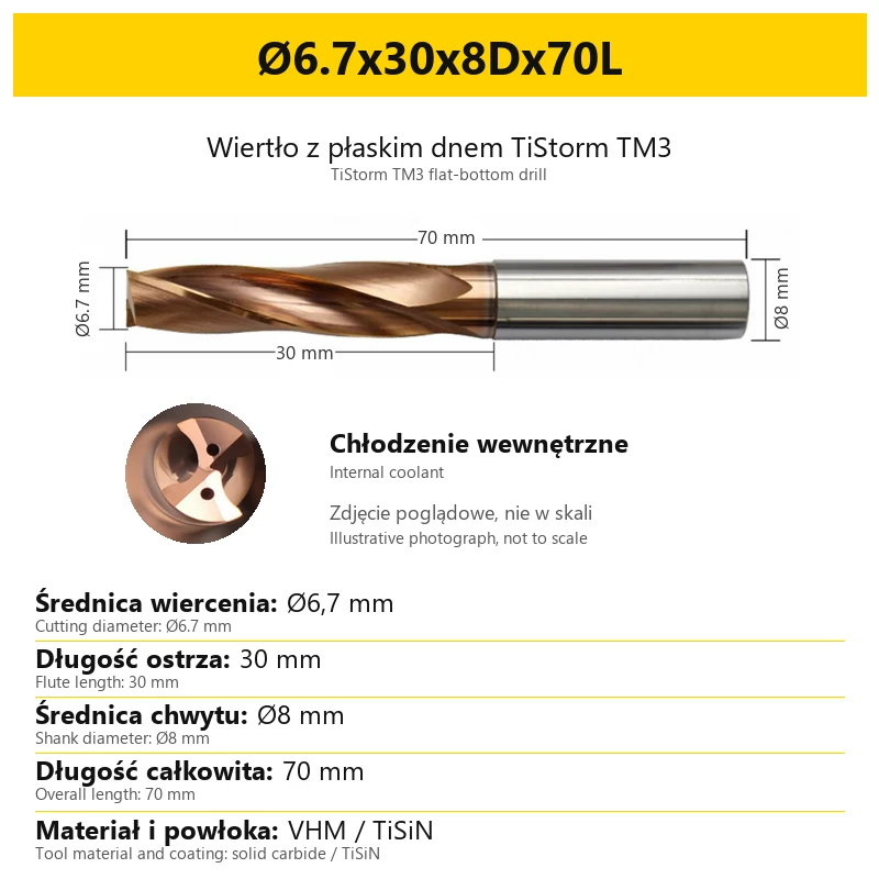
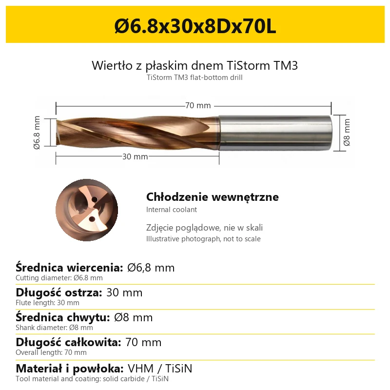
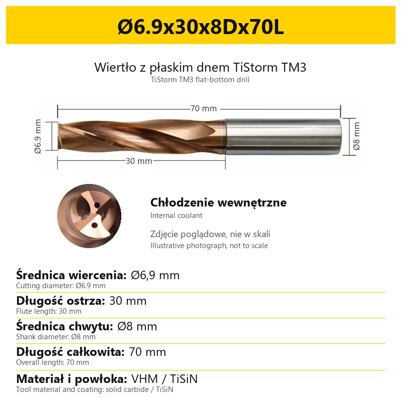
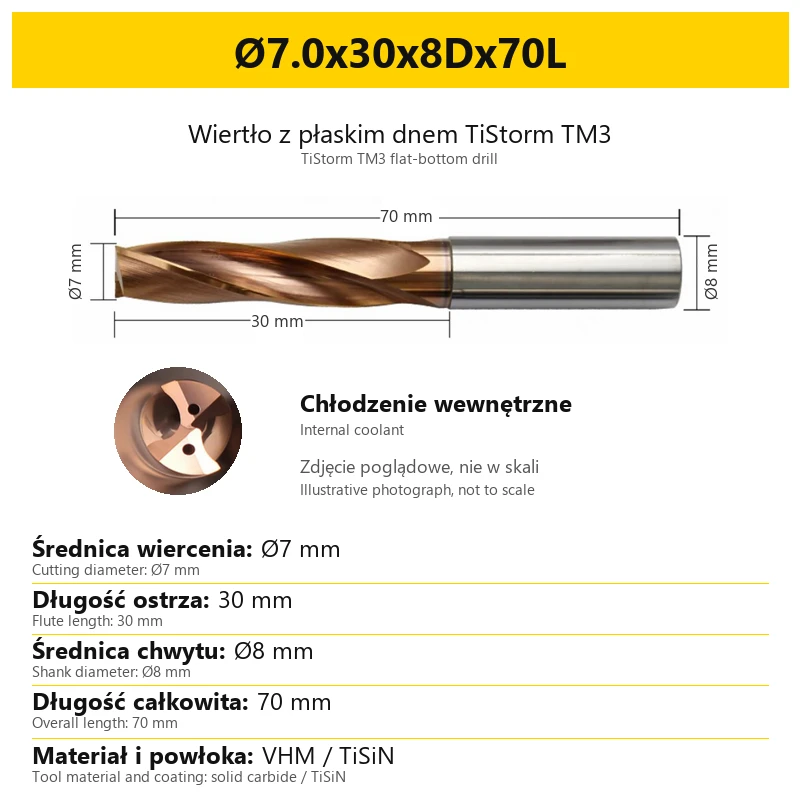
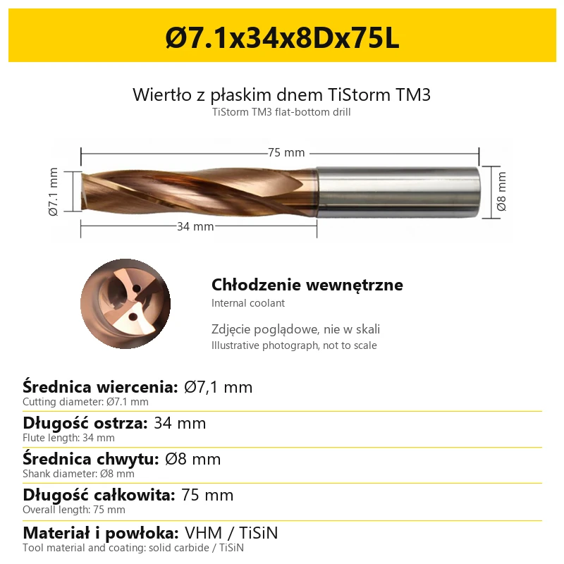
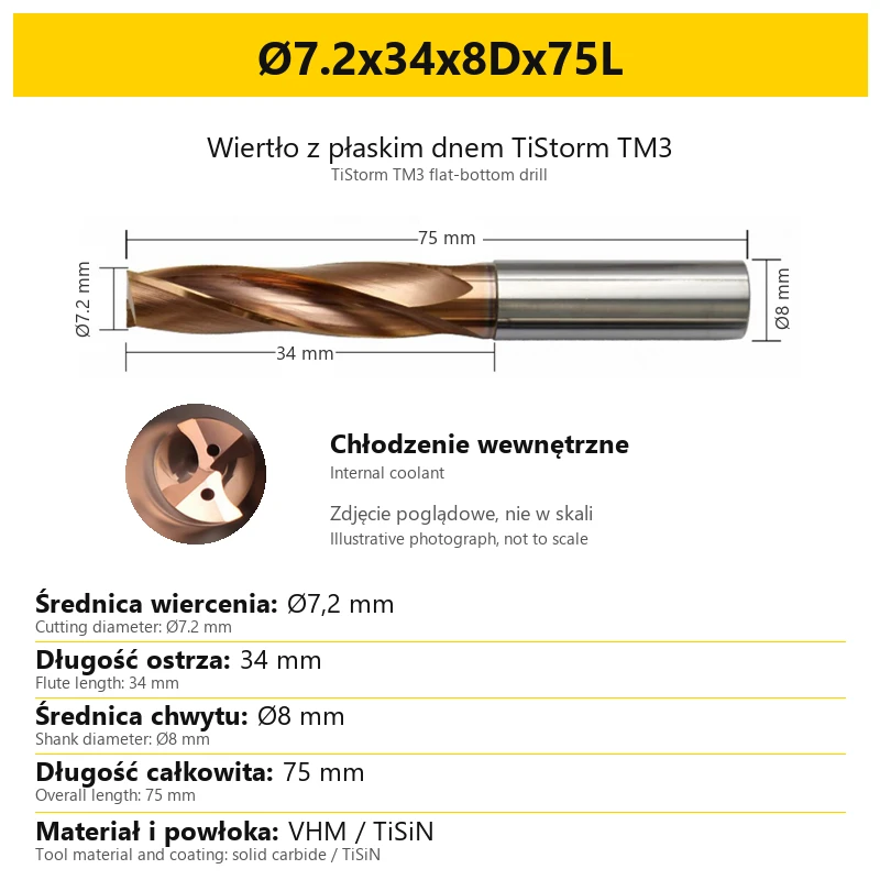
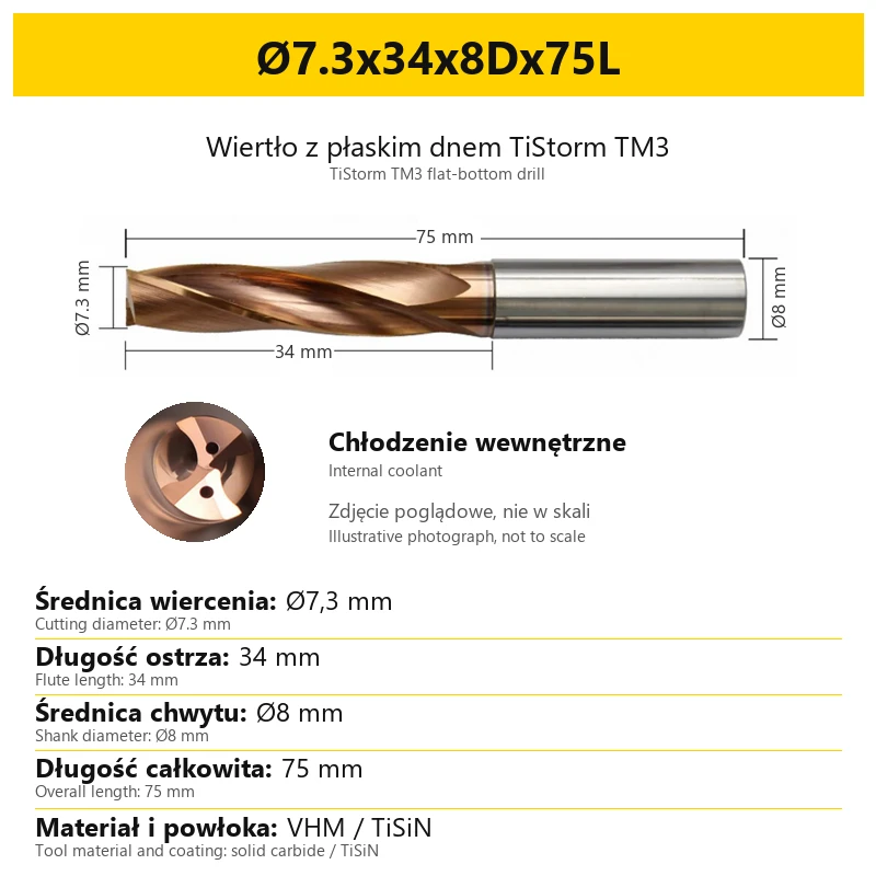
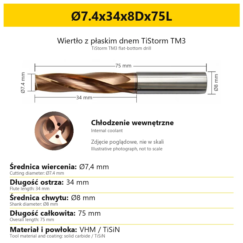
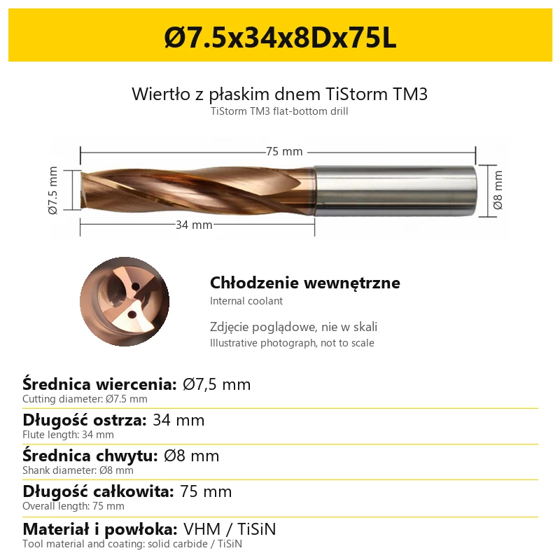
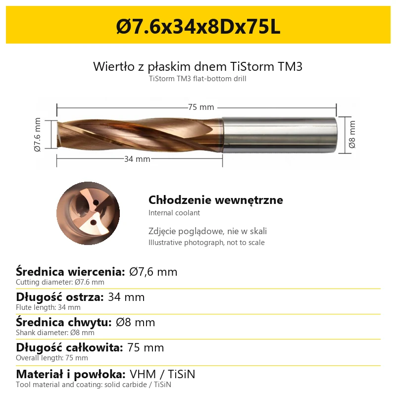
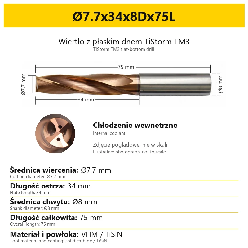
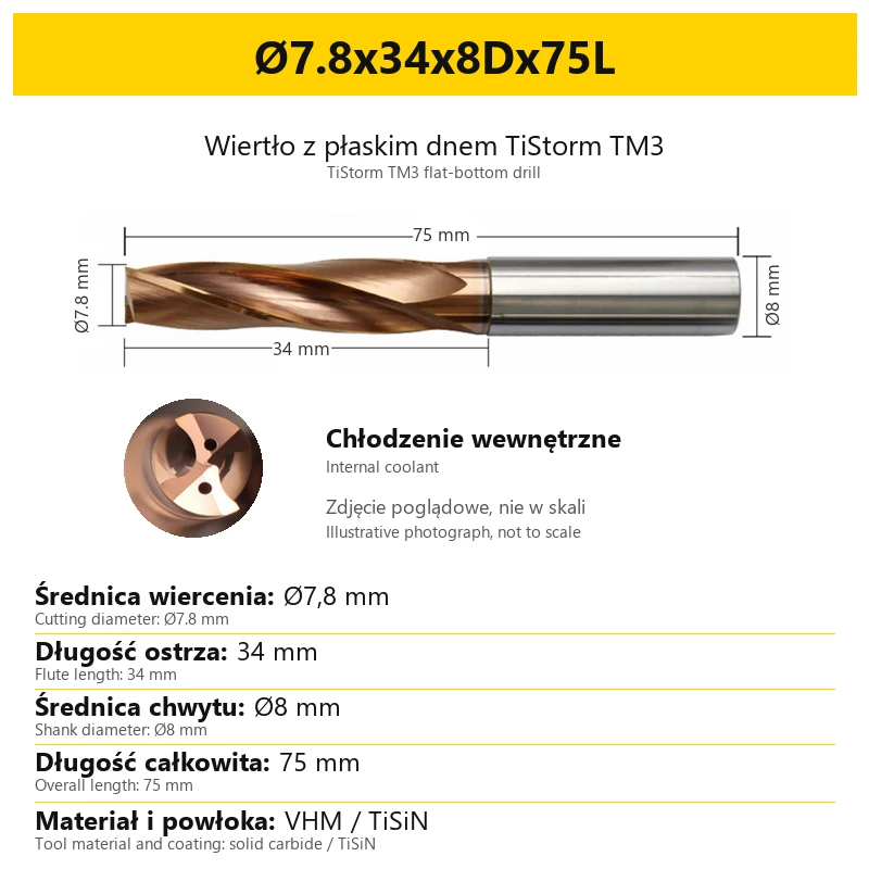
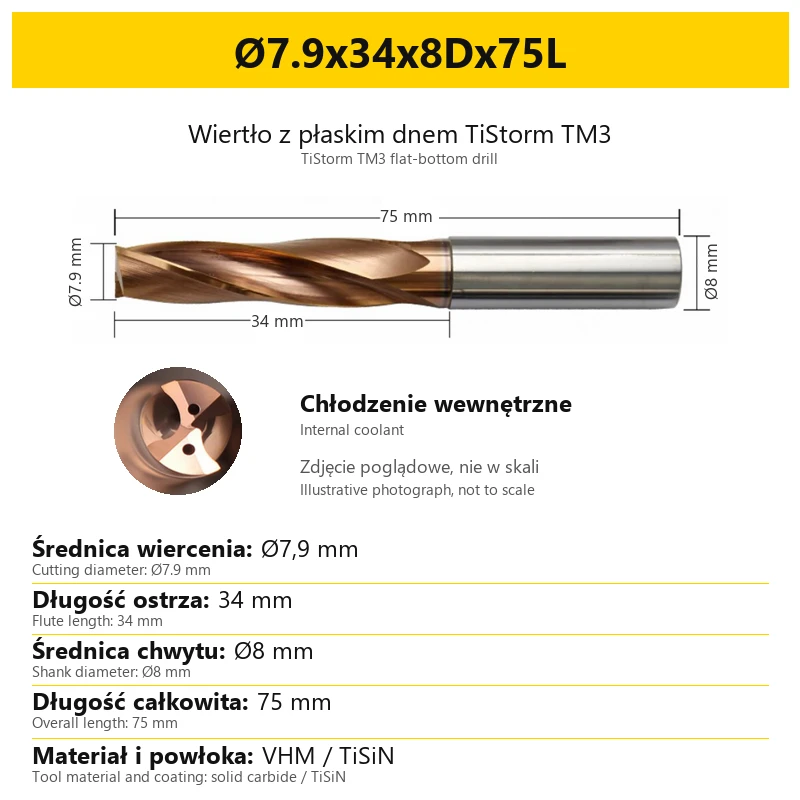
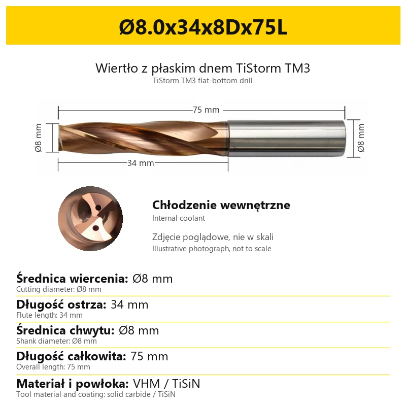
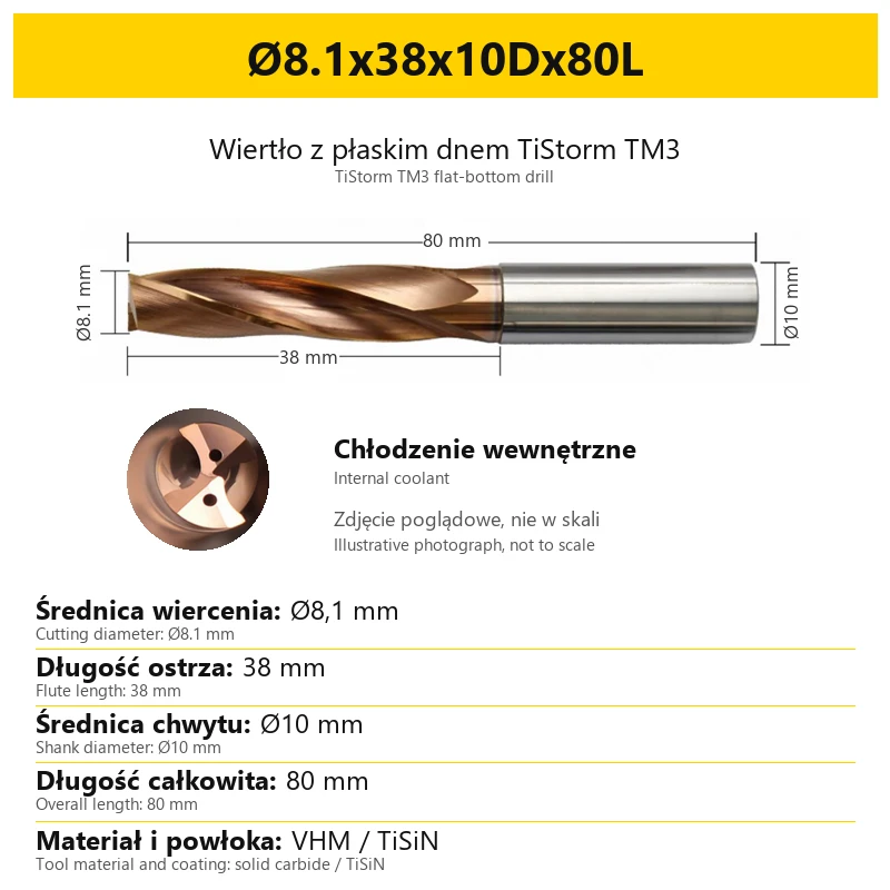
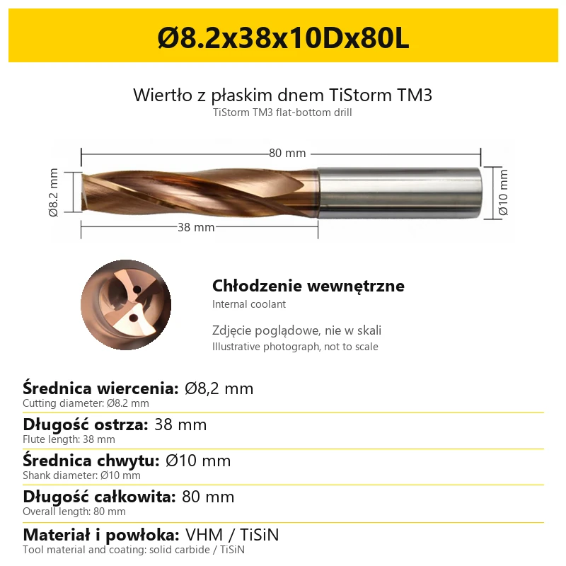
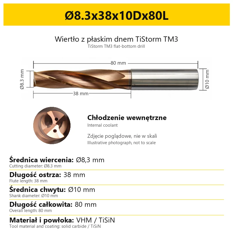
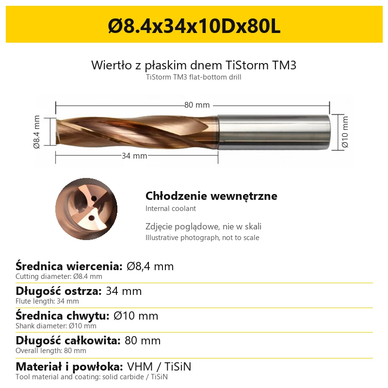
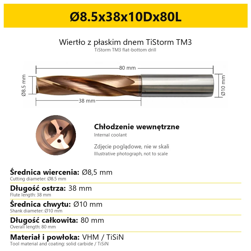
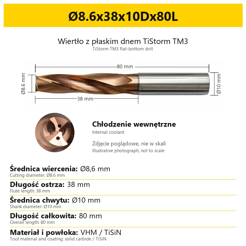
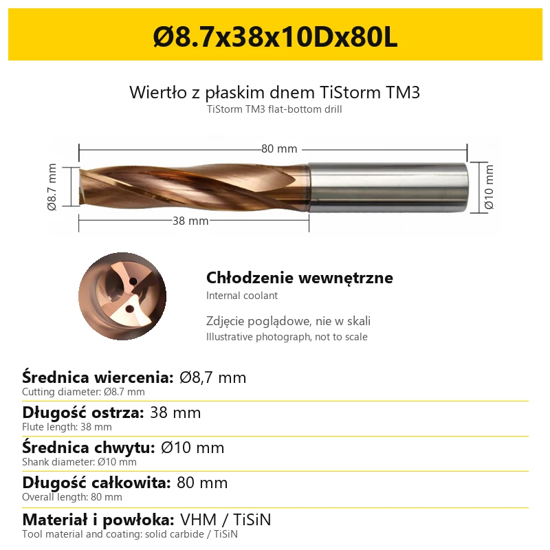
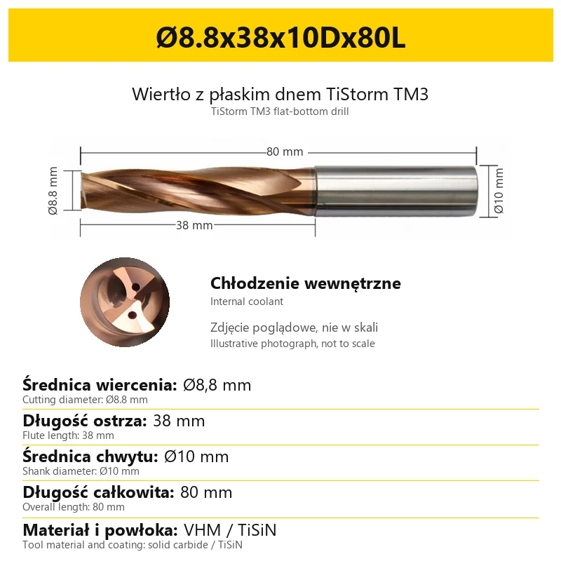
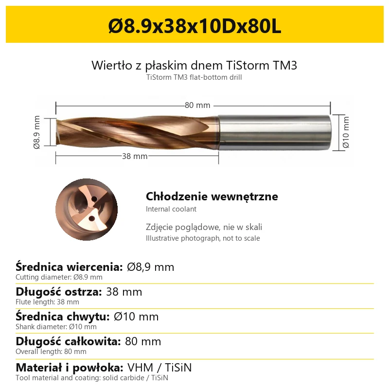
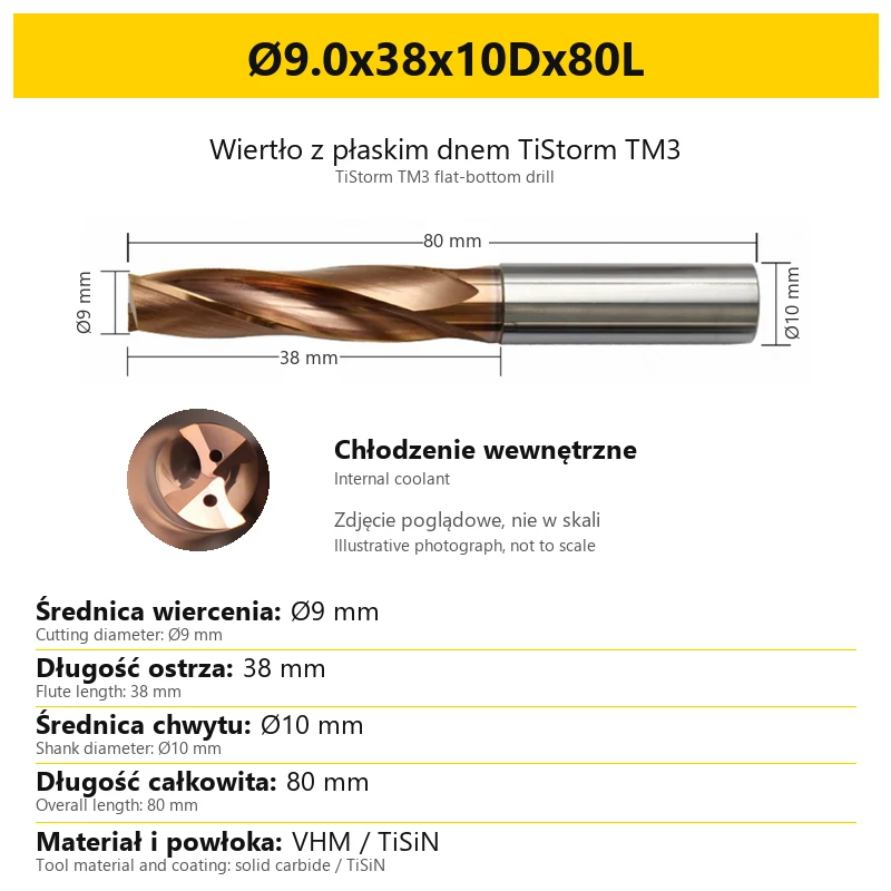
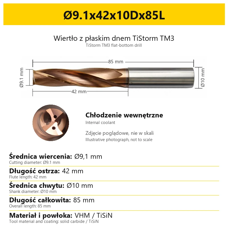
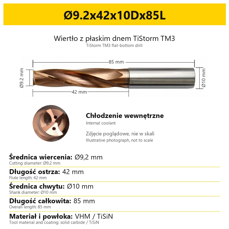
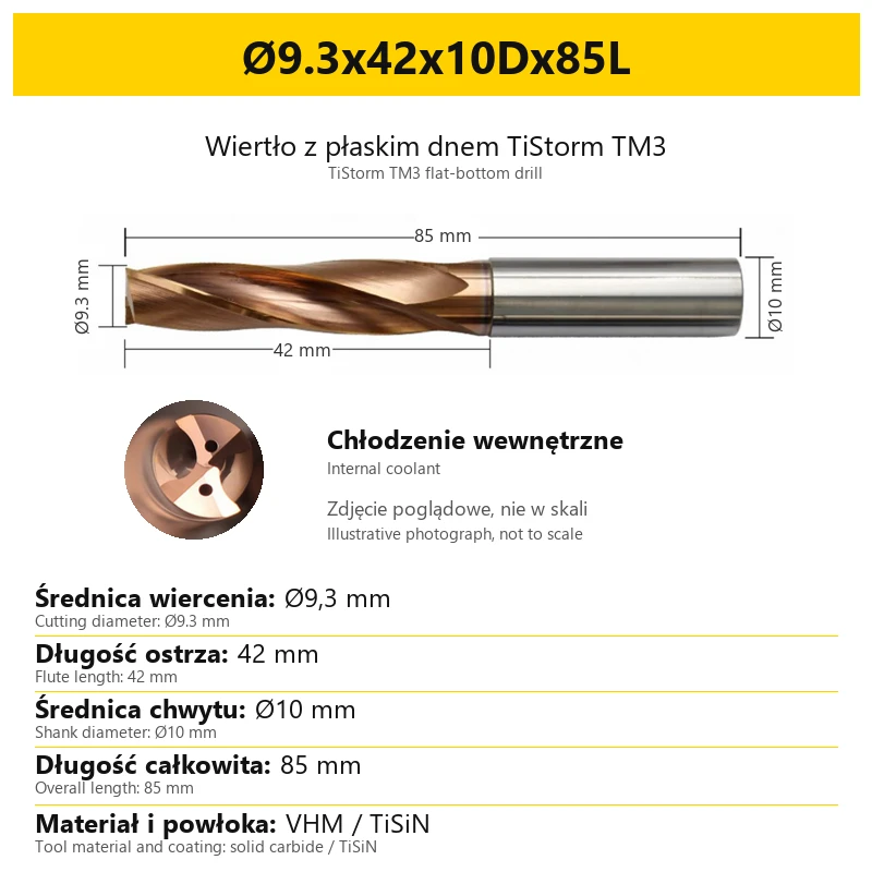
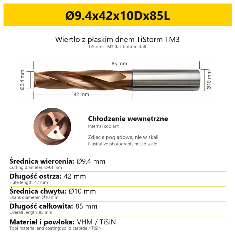
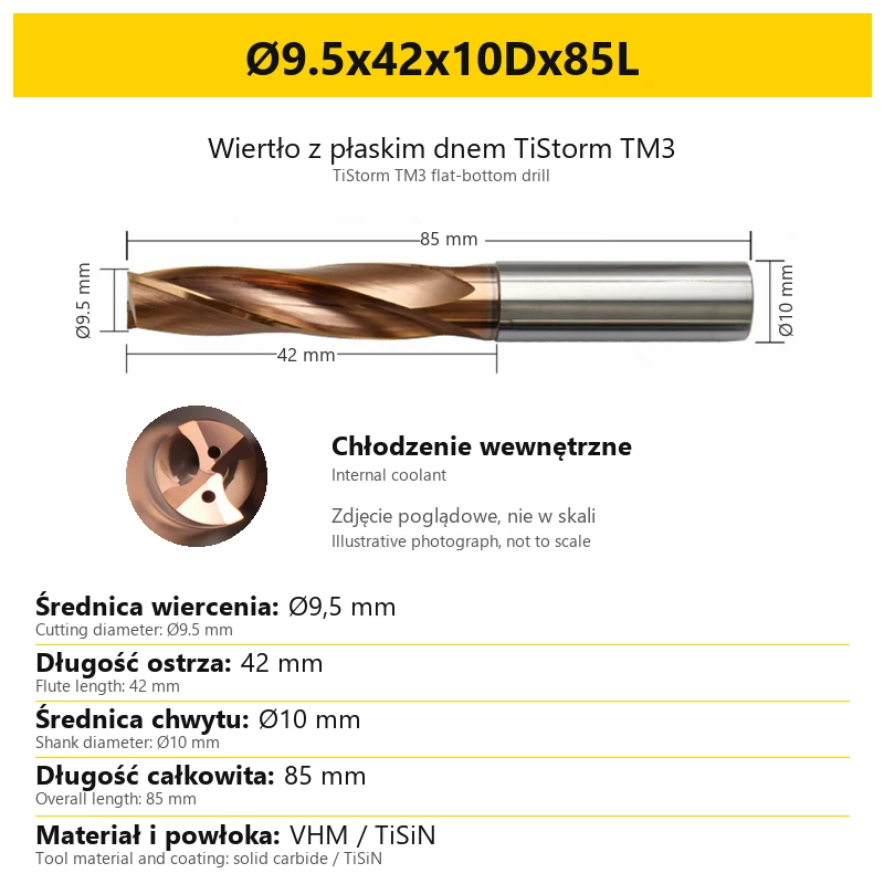
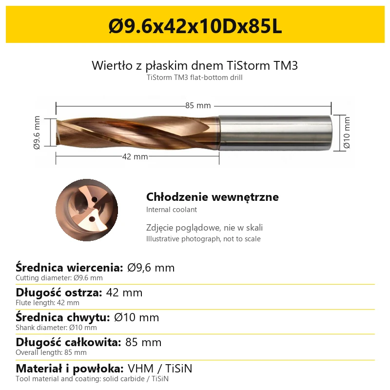
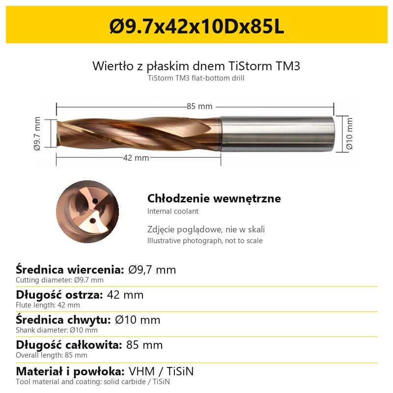
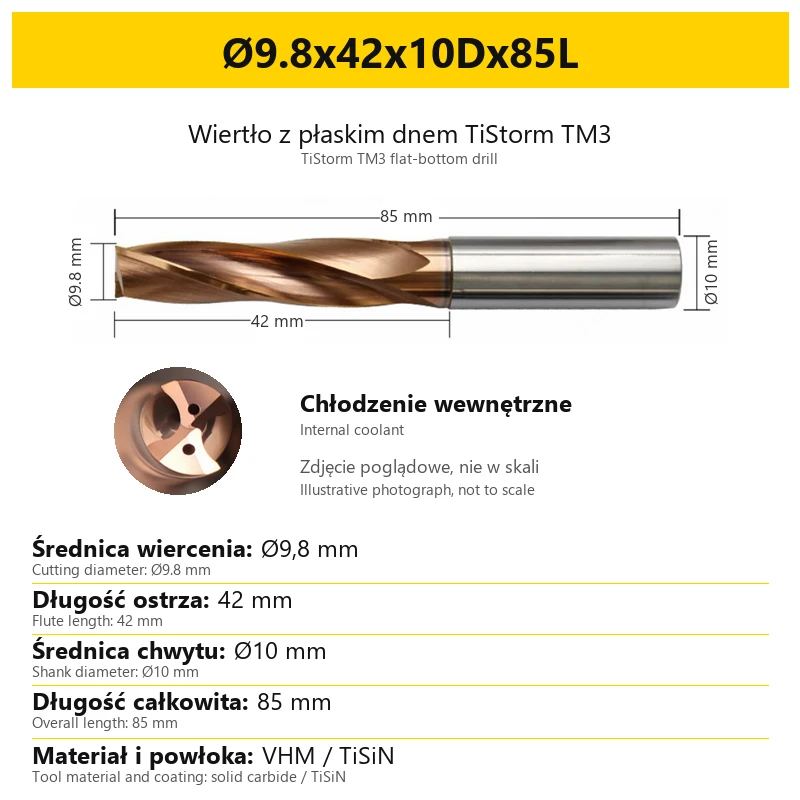
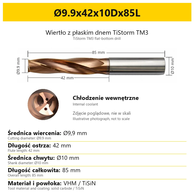
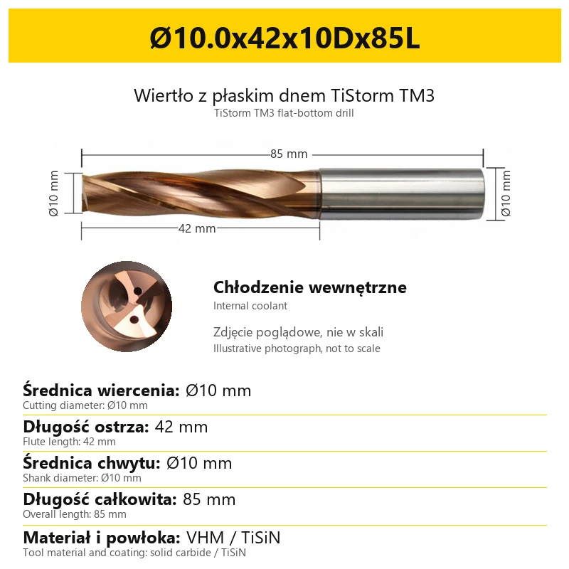
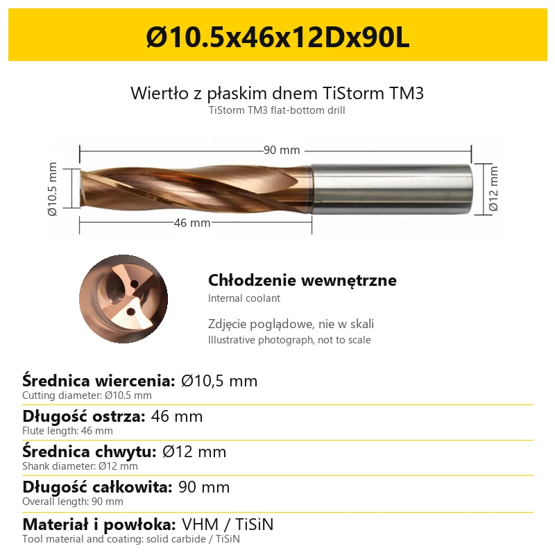
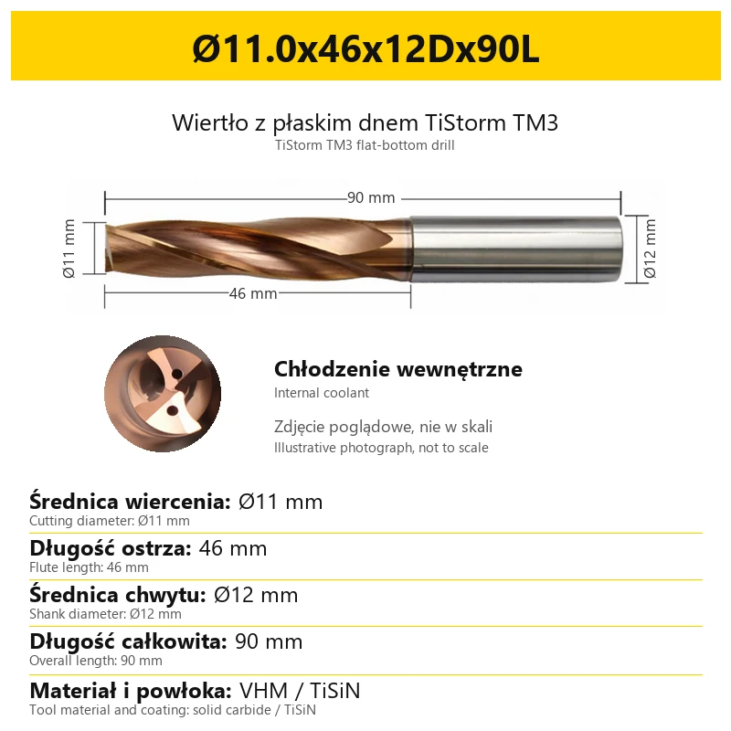
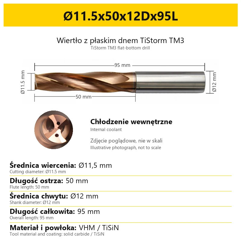
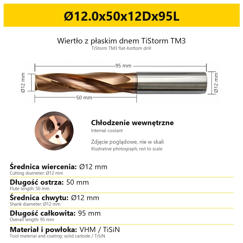
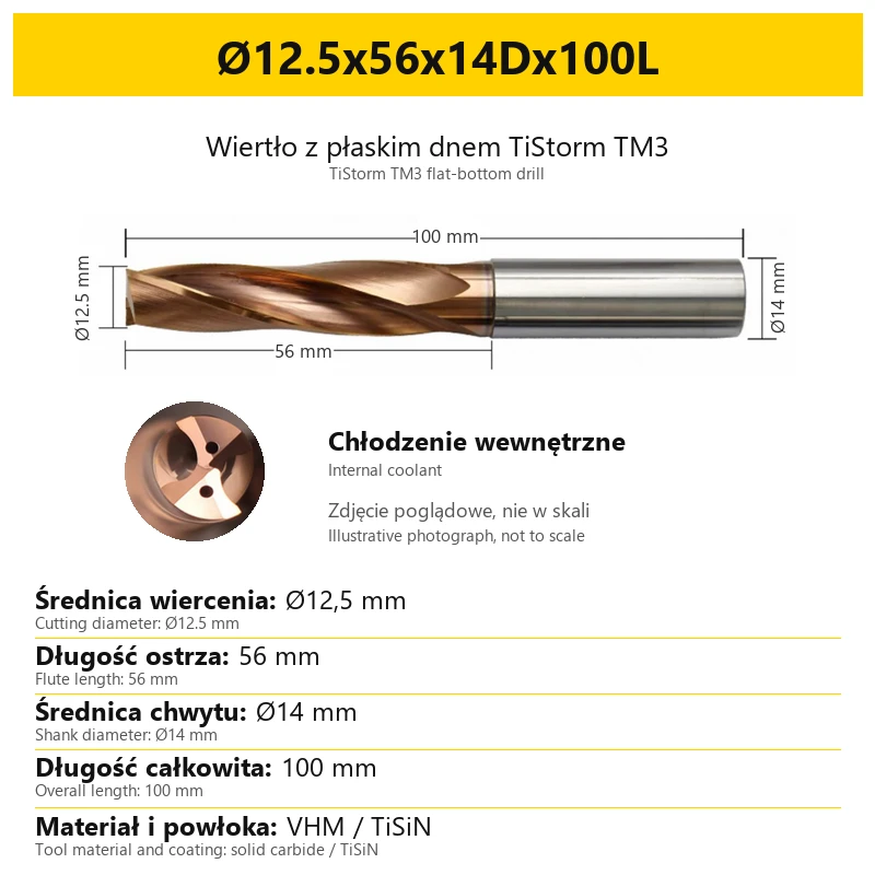
In this version, coolant is delivered through the tool to outlets near the cutting edges. The circular close-up on each card shows the point and coolant channels, helping identify the internal-coolant design.
Before selection, check that the machine and toolholder can supply coolant through the drill shank. Matching the shank diameter alone does not confirm a functioning internal coolant path. Pressure and flow need to suit the operation; this listing does not assign one value to all diameters.
5. Reading the size designation
The variant name lists four dimensions in sequence. All values are in millimetres. The letter D in the third part identifies the shank, while the final letter L identifies overall length.
| Position in the designation | Meaning |
|---|---|
| First value, preceded by Ø | Cutting diameter |
| Second value | Flute length — the fluted cutting portion |
| Third value, next to D | Cylindrical shank diameter — used to select the toolholding size |
| Final value, next to L | Overall drill length |
The shank can be larger than the cutting diameter. Do not select the toolholder using only the first number in the designation. Flute length and overall length are also separate dimensions; neither should be measured from the photograph.
6. Sizes and selection
| Dimension | Series range |
|---|---|
| Cutting diameter | Ø3–14 mm |
| Flute length | 15–60 mm, depending on the selected size |
| Shank diameter | Ø4, Ø6, Ø8, Ø10, Ø12 or Ø14 mm — as specified by the variant designation |
| Overall length | 55–105 mm |
The complete set of dimensions is stated in the selected variant and on its card. The ranges in this table describe the product family; they do not imply that every diameter is available with every length or shank.
Match the hole diameter and depth to the workpiece grade, hardness, entry and exit geometry, and available coolant supply. Flute length describes the tool but does not, on its own, guarantee an allowable drilling depth for every operation.
For selection assistance, provide the workpiece grade and hardness, hole diameter and depth, surface geometry and toolholding diameter. This helps distinguish the cutting diameter from the shank diameter when choosing the tool.
7. Scope of supply and photographs
The sale unit is one TiStorm TM3 drill in the selected size. It has an integral carbide cutting portion and is not an indexable-insert drill body.
The cards use a shared illustrative photograph of this product family, with values assigned to the individual variant. The full-tool image and coolant close-up show the construction; photographic proportions are not intended for measuring length. Use the variant designation and labelled values to select the size.
8. Frequently asked questions
Can this drill be used for side milling?
No. TiStorm TM3 is intended for axial-feed operations. Its flat point does not make it suitable for use as an end mill with a transverse feed.
Will it produce a perfectly flat bottom?
The geometry produces a substantially flat bottom that may retain slight concavity. If the workpiece drawing specifies a particular flatness tolerance or bottom finish, account for that requirement when selecting the machining process.
Does 55 HRC describe the drill hardness?
No. It refers to the hardness range of the workpiece. The drill is made from solid carbide and has a TiSiN coating.
Does every size have internal coolant channels?
Yes. The variants in this listing are the internal-coolant version. To use this feature, coolant must be supplied through the machine and suitable toolholding equipment.
Related products
-
C76A-92787

 Flat Bottom Drills 0.00
Flat Bottom Carbide Drill VHM 55HRC TiSiN TiStorm TM1


Bestsellers
-
Bestseller
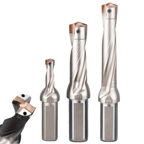
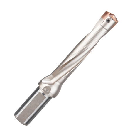
JCD modular drill with replaceable tip - internal cooling, for deep holes | GrotXD
JCD C20-100-3D Ø10~10.9 JCD C20-110-3D Ø11~11.9 JCD C20-120-3D Ø12~12.9 JCD C20-130-3D Ø13~13.9 JCD C20-140-3D Ø14~14.9 + 61 morePrice €69.52Price €56.52without VAT -
Price €17.09Price €13.90without VAT
-
Price €7.07Price €5.74without VAT
-
Price €7.52Price €6.12without VAT
-
Bestseller
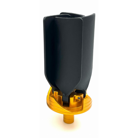
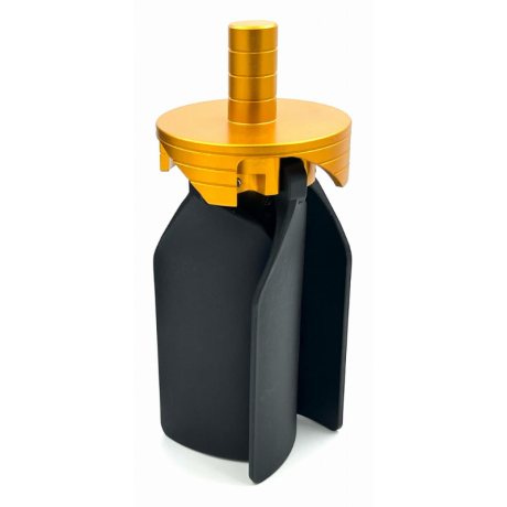 Other Accessories 0.00
CNC Chip Fan / Chip Blower
Complete CNC chip fan Kit: blades, springs, pins and screwsPrice €53.56Price €43.55without VAT -
Bestseller
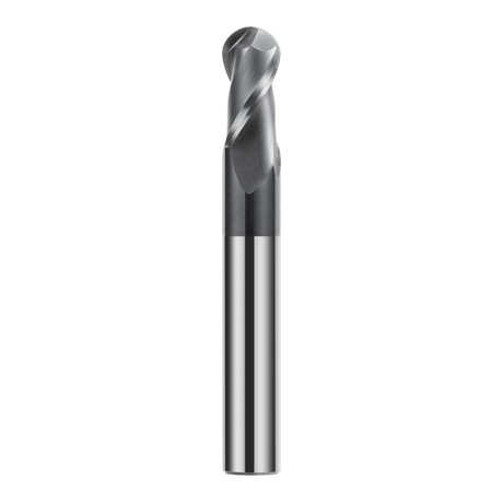
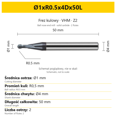 Ball Nose End Mills 0.00
2-Flute Carbide Ball Nose End Mill - HYPERCUT
Ø1xR0.5x4Dx50L Ø1.5xR0.75x4Dx50L Ø2xR1x4Dx50L Ø2.5xR1.25x4Dx50L Ø3xR1.5x3Dx50L + 26 morePrice €10.09Price €8.21without VAT -
Bestseller
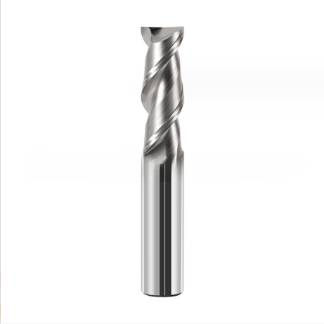
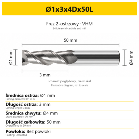 2-Flute End Mills 0.00
2-Flute Carbide End Mill for Aluminium
Ø1x3x4Dx50L Ø1.5x4x4Dx50L Ø2x6x4Dx50L Ø2.5x7.5x4Dx50L Ø3x9x3Dx50L + 31 morePrice €5.33Price €4.33without VAT -
Bestseller
 2-Flute End Mills 0.00
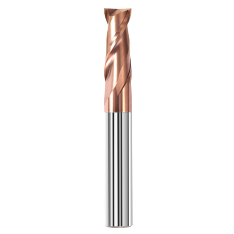
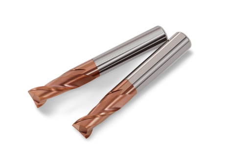
2-Flute Carbide End Mill for Steel 55 HRC - TiSiN - Solid Carbide
Ø6x24x6Dx75L Ø8x25x8Dx75L Ø4x20x4Dx100L Ø5x30x5Dx100L Ø6x30x6Dx100L + 31 morePrice €4.38Price €3.56without VAT -
Bestseller
 Ball Nose End Mills 0.00
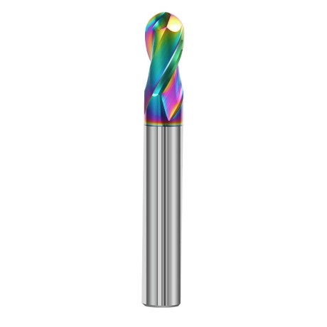
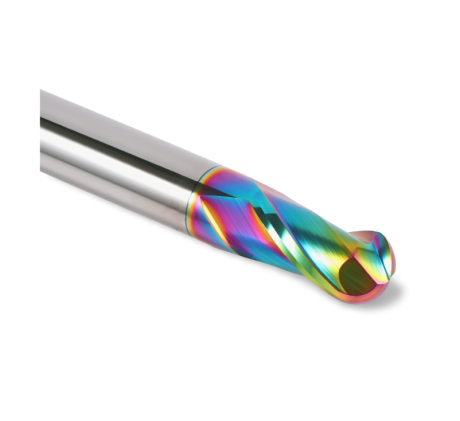
2-Flute DLC Coated Carbide Ball Nose End Mill| DuraEdge Alu
Ø1.0xR0.5x4Dx50L Ø1.5xR0.75x4Dx50L Ø2.0xR1x4Dx50L Ø2.5xR1.25x4Dx50L Ø3.0xR1.5x3Dx50L + 34 morePrice €7.85Price €6.38without VAT -
Bestseller
 2-Flute End Mills 0.00
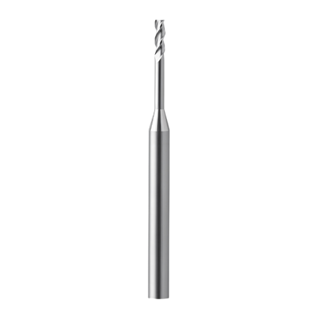
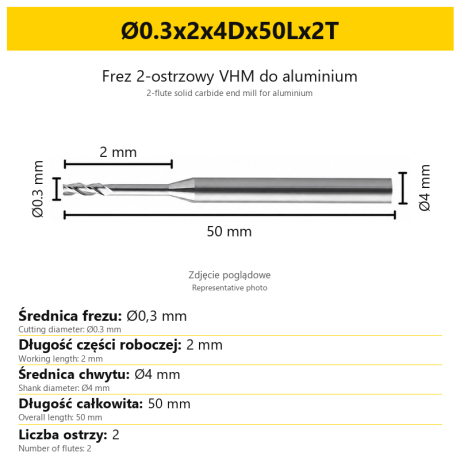
2-Flute End Mill for Aluminium | VHM | Miniature Ø0.3 - Ø0.9
Ø0.3x2x4Dx50Lx2T Ø0.3x3x4Dx50Lx2T Ø0.3x4x4Dx50Lx2T Ø0.4x2x4Dx50Lx2T Ø0.4x3x4Dx50Lx2T + 28 morePrice €7.95Price €6.47without VAT -
Bestseller
 Ball Nose End Mills 0.00
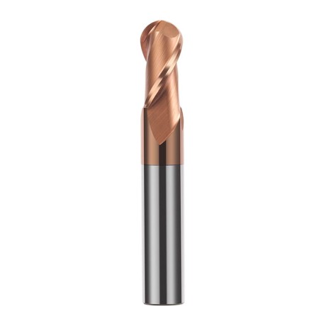
2-Flute TiSiN Coated Carbide Ball Nose End Mill
Ø1xR0.5x4Dx50L Ø1.5xR0.75x4Dx50L Ø2xR1x4Dx50L Ø2.5xR1.25x4Dx50L Ø3xR1.5x3Dx50L + 38 morePrice €7.24Price €5.89without VAT -
Bestseller
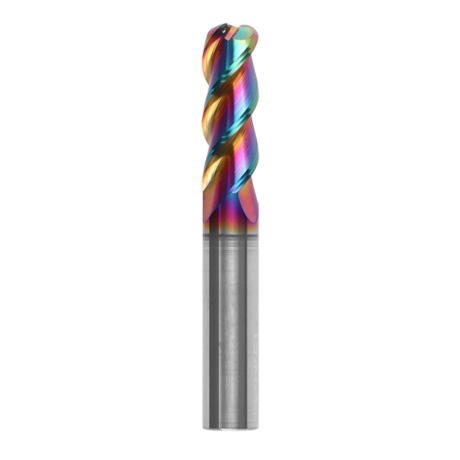
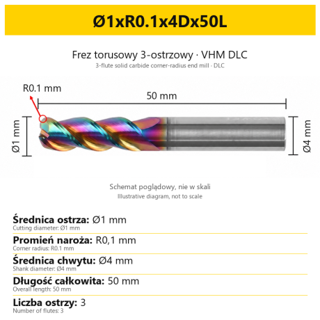
3-Flute Carbide Corner Radius End Mill for Aluminium| AL DLC
Ø1xR0.1x4Dx50L Ø1xR0.2x4Dx50L Ø1xR0.3x4Dx50L Ø1.5xR0.1x4Dx50L Ø1.5xR0.2x4Dx50L + 137 morePrice €5.89Price €4.79without VAT -
Bestseller
 3-Flute End Mills 0.00
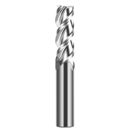
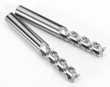
3-Flute Carbide End Mill VHM Z-3 for Aluminium| TriMill AL
Ø1x3xD4x50L Ø1.5x5x4Dx50L Ø2x6x4Dx50L Ø2.5x8x4Dx50L Ø3x9x3Dx50L + 41 morePrice €5.08Price €4.13without VAT -
Bestseller
 Countersinks 0.00
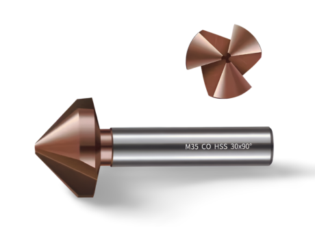
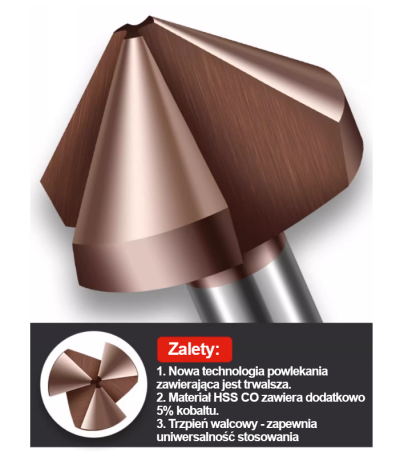
3-Flute Countersink Fi4.5-fi60, 90° - HSS-CO - 5% Kobaltu | Straight Shank
Ø4.5 x 4 x 90° x 40L Ø5 x 5 x 90° x 45L Ø6.3 x 5 x 90° x 45L Ø8.3 x 6 x 90° x 50L Ø10.4 x 6 x 90° x 50L + 12 morePrice €4.79Price €3.89without VAT -
Bestseller
 3-Flute End Mills 0.00
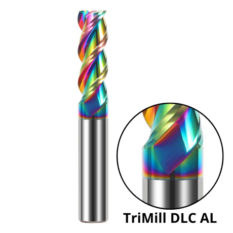
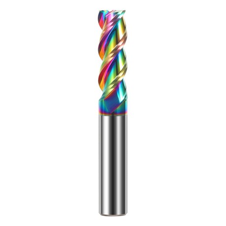
3-Flute DLC Coated Carbide End Mill | TriMill DLC AL
Ø1x3x4Dx50L Ø1.5x5x4Dx50L Ø2x6x4Dx50L Ø2.5x8x4Dx50L Ø3x8x3Dx50L + 38 morePrice €5.05Price €4.10without VAT -
Bestseller

 3-Flute End Mills 0.00
3-Flute HRC65 DLC Coated Carbide End Mill, U-Shaped Flute, for Aluminium | DuraEdge3 Alu
Ø1x3x4Dx50L Ø1.5x5x4Dx50L Ø2x6x4Dx50L Ø2.5x8x4Dx50L Ø3x9x3Dx50L + 40 morePrice €6.73Price €5.47without VAT