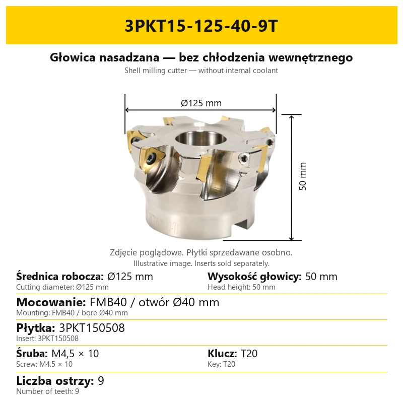
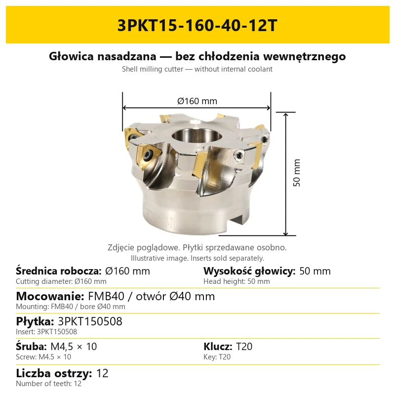
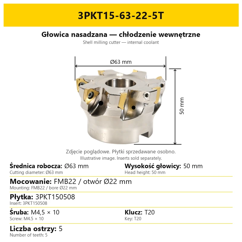


Milling Head for 3PKT Inserts without Coolant / with Internal Coolant
Shipping costs are not included in the price.
Shipping costs are not included in the price.

Weekly deals
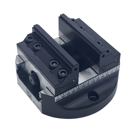
5-axis vise with hard jaws
Self-centering machine vise. Hard jaws included.
excl. VAT
Regular price:
Lowest price in the 30 days before the reduction:
Time left
Offer ends 06.11.2026 23:59. Offer applies to the vise + hard jaws bundle only.
Ask about the product

The administrator of personal data is Kortools. We process it to respond to your inquiry. More information regarding the processing of personal data can be found in privacy policy.
Select a product variant:
Individual variants may differ in price
Product code: A25F-4941E
Product description
1. Shell milling cutter for 3PKT inserts
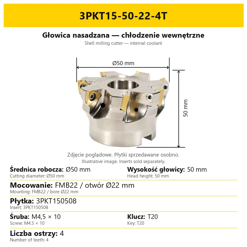
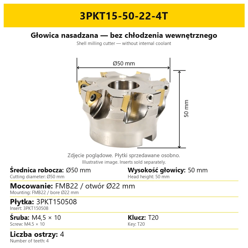
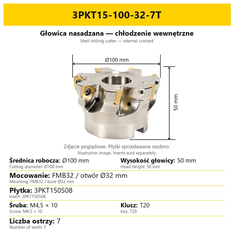
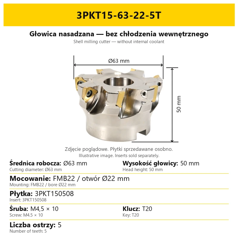
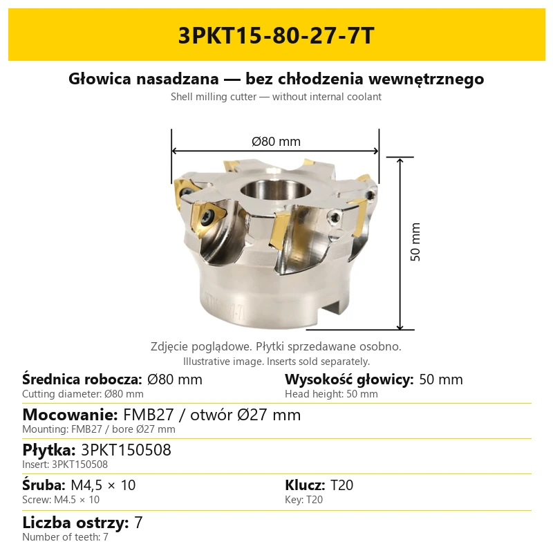
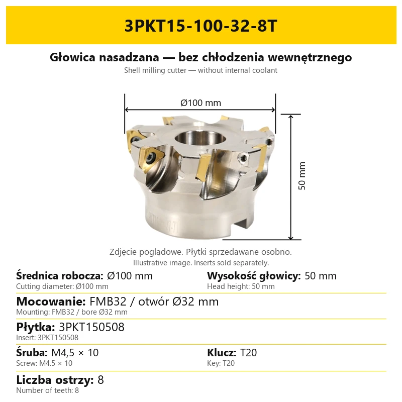
This shell milling cutter uses replaceable 3PKT150508 inserts and FMB mounting. It is offered without internal coolant or with channels supplying coolant to the cutting head.
The body is made of 42CrMo alloy steel. Induction hardening provides hardness and resistance to deformation. Screws secure the inserts in their pockets.
| Parameter | Information |
|---|---|
| Tool type | Shell milling cutter |
| Body material | 42CrMo alloy steel |
| Heat treatment | Induction hardening |
| Insert | 3PKT150508 |
| Mounting | FMB, matched to the bore diameter |
Cutting inserts are sold separately. Images show inserts fitted to illustrate their position in the pockets. This does not mean inserts are supplied with the body.
2. Applications and insert selection
This tool family is intended for roughing and finishing. Applications include face, shoulder and side milling. Compare the selected cutter geometry, mounting dimensions and insert type before making a selection.
| Selection factor | Purpose |
|---|---|
| Body and mounting | Define the cutting diameter and the connection to the toolholder. |
| Replaceable insert | Its type must match the pocket of the selected body. |
| Insert grade and geometry | Selected for the workpiece material and type of operation. |
| Number of teeth | Specified in the designation and on the particular variant card. |
The body code does not specify the insert grade. When purchasing inserts, consider the workpiece material and required operation; the cutter card identifies the matching insert type.
3. Coolant and configuration identification
Choose the coolant configuration separately from the cutting diameter. Cards for internal-coolant heads carry a clear label. Cards for heads without internal coolant identify that configuration in the tool-type heading.
| Configuration | Identification | Selection |
|---|---|---|
| Without internal coolant | Configuration label on the cutter card. | Compare cutting diameter, FMB bore and tooth count. |
| With internal coolant | Configuration label. | Also check coolant supply through the appropriate mounting. |
The size code alone does not always distinguish heads with and without internal coolant. Heads with the same diameter may also have different tooth counts. Compare the configuration heading and the complete variant card when choosing.
4. Dimensions and FMB mounting
| Parameter | Range / meaning |
|---|---|
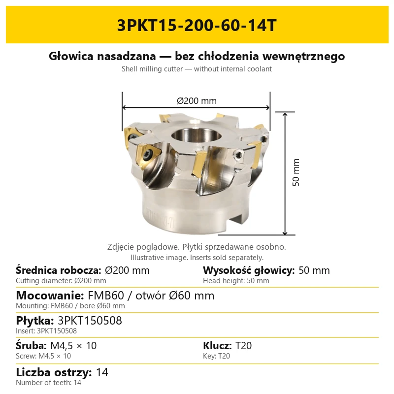
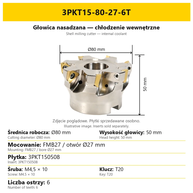
| Cutting diameter | Ø50–Ø200 mm, depending on configuration |
| Mounting bore | Ø22, Ø27, Ø32, Ø40 or Ø60 mm |
| Mounting | FMB22, FMB27, FMB32, FMB40 or FMB60 |
| Head height | 50 mm |
| Number of teeth | From 4 to 14, as specified on the selected configuration card |
The listing diameter range does not mean that every coolant configuration is offered in every size. The selected variant defines the complete combination of cutting diameter, bore, tooth count and coolant arrangement.
Cutting diameter is different from mounting bore diameter. For example, FMB22 corresponds to a Ø22 mm bore, independently of the cutting diameter of the particular head.
Images are illustrative. Select the tool using the dimensions and designation of the chosen variant rather than proportions in the photograph. The variant card states the cutting diameter, head height, mounting bore and number of teeth.
5. Reading the cutter designation
Example: 3PKT15-80-27-6T. Read the designation together with the configuration label on the card.
| Code element | Meaning in the example |
|---|---|
| 3PKT15 | Body family for 3PKT150508 inserts |
| 80 | Ø80 mm cutting diameter |
| 27 | Ø27 mm mounting bore / FMB27 |
| 6T | Six teeth |
The number before T specifies the teeth on one body. It is not the number of heads or inserts included in an order. Check the configuration label for the coolant arrangement.
6. Inserts and pocket servicing
| Component | Designation | Purpose |
|---|---|---|
| Insert | 3PKT150508 | Replaceable cutting edge for the head. |
| Insert screw | M4.5 × 10 | Secures the insert in its pocket. |
| Key | T20 | Operates the insert screw. |
Accurate insert fit and seating are part of the cutter design. During servicing, check insert contact and the condition of the screw and pocket. Select the insert grade for the workpiece material and operation.
The M4.5 × 10 screw secures an insert rather than the complete head to its arbor. The insert screw designation and FMB bore describe two different connections.
Cutting inserts are sold separately. Images show inserts fitted to illustrate their position in the pockets. This does not mean inserts are supplied with the body.
7. Insert wear and machining checks
The condition of replaceable inserts affects part dimensions and surface quality. The following points distinguish common symptoms; process settings must be related to the workpiece material, insert and clamping rigidity.
| Symptom | What to check |
|---|---|
| Gradual surface deterioration or dimensional change | Insert flank wear and cutting speed. For excessive wear, review the cutting parameters and insert grade. |
| Edge chipping | Insert selection, machining parameters, workpiece rigidity and correct insert clamping. |
| Sudden insert or tool failure | Insert seating, vibration, setup rigidity and loading from feed and cutting conditions. |
| Built-up edge and uneven surface | Cutting speed, feed and insert sharpness. Adjust parameters and cutting-edge geometry for the workpiece material. |
Do not use one set of parameters for all workpiece materials and insert grades. T denotes the number of teeth, not a recommended spindle speed or feed.
8. Questions and answers
How do I identify the internal-coolant configuration?
Its card has an internal-coolant label.
Does the same code always identify the same coolant configuration?
No. Also compare the configuration heading and image assigned to the variant.
Does FMB22 mean a Ø22 mm cutting head?
No. It denotes mounting with a Ø22 mm bore. Cutting diameter is stated separately.
Are inserts included?
No. 3PKT150508 inserts are sold separately from the cutter body.
Do two heads of the same diameter have the same tooth count?
Not necessarily. Check the number next to T and on the selected configuration card.
Bestsellers
-
Bestseller
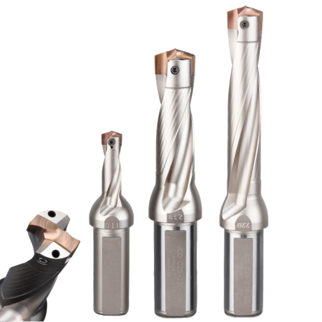
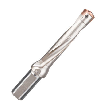
JCD modular drill with replaceable tip - internal cooling, for deep holes | GrotXD
JCD C20-100-3D Ø10~10.9 JCD C20-110-3D Ø11~11.9 JCD C20-120-3D Ø12~12.9 JCD C20-130-3D Ø13~13.9 JCD C20-140-3D Ø14~14.9 + 61 morePrice €69.52Price €56.52without VAT -
Price €17.09Price €13.90without VAT
-
Price €7.07Price €5.74without VAT
-
Price €7.52Price €6.12without VAT
-
Bestseller
 Other Accessories 0.00
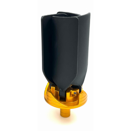
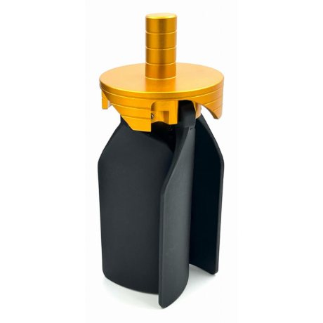
CNC Chip Fan / Chip Blower
Complete CNC chip fan Kit: blades, springs, pins and screwsPrice €53.56Price €43.55without VAT -
Bestseller
 Ball Nose End Mills 0.00
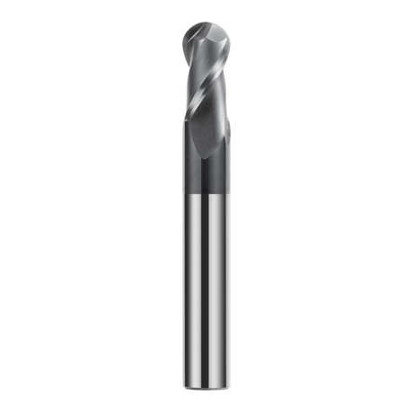
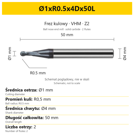
2-Flute Carbide Ball Nose End Mill - HYPERCUT
Ø1xR0.5x4Dx50L Ø1.5xR0.75x4Dx50L Ø2xR1x4Dx50L Ø2.5xR1.25x4Dx50L Ø3xR1.5x3Dx50L + 26 morePrice €10.09Price €8.21without VAT -
Bestseller
 2-Flute End Mills 0.00
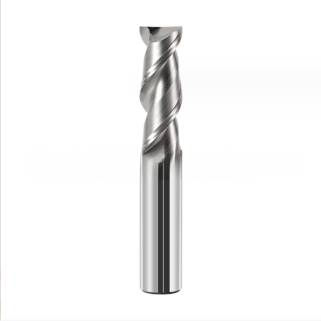
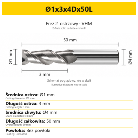
2-Flute Carbide End Mill for Aluminium
Ø1x3x4Dx50L Ø1.5x4x4Dx50L Ø2x6x4Dx50L Ø2.5x7.5x4Dx50L Ø3x9x3Dx50L + 31 morePrice €5.33Price €4.33without VAT -
Bestseller
 2-Flute End Mills 0.00
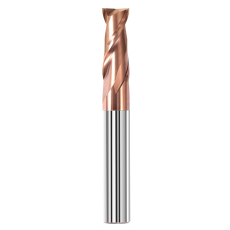
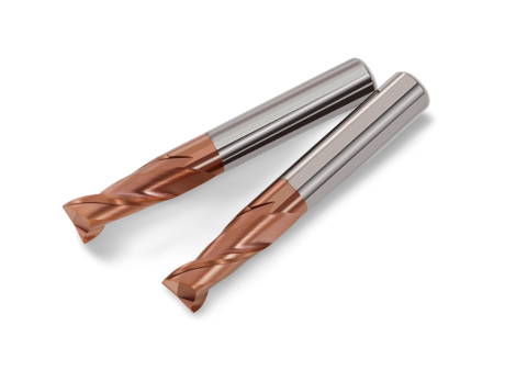
2-Flute Carbide End Mill for Steel 55 HRC - TiSiN - Solid Carbide
Ø6x24x6Dx75L Ø8x25x8Dx75L Ø4x20x4Dx100L Ø5x30x5Dx100L Ø6x30x6Dx100L + 31 morePrice €4.38Price €3.56without VAT -
Bestseller
 Ball Nose End Mills 0.00
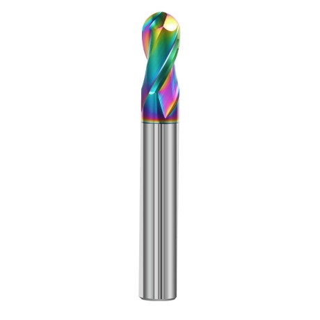
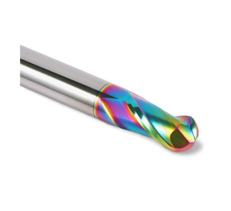
2-Flute DLC Coated Carbide Ball Nose End Mill| DuraEdge Alu
Ø1.0xR0.5x4Dx50L Ø1.5xR0.75x4Dx50L Ø2.0xR1x4Dx50L Ø2.5xR1.25x4Dx50L Ø3.0xR1.5x3Dx50L + 34 morePrice €7.85Price €6.38without VAT -
Bestseller
 2-Flute End Mills 0.00
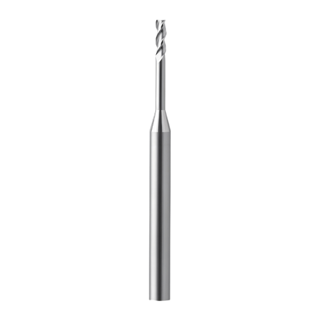
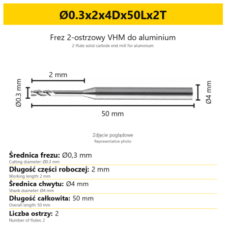
2-Flute End Mill for Aluminium | VHM | Miniature Ø0.3 - Ø0.9
Ø0.3x2x4Dx50Lx2T Ø0.3x3x4Dx50Lx2T Ø0.3x4x4Dx50Lx2T Ø0.4x2x4Dx50Lx2T Ø0.4x3x4Dx50Lx2T + 28 morePrice €7.95Price €6.47without VAT -
Bestseller
 Ball Nose End Mills 0.00
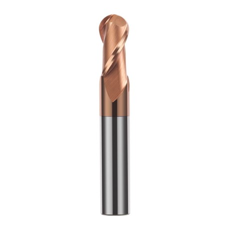
2-Flute TiSiN Coated Carbide Ball Nose End Mill
Ø1xR0.5x4Dx50L Ø1.5xR0.75x4Dx50L Ø2xR1x4Dx50L Ø2.5xR1.25x4Dx50L Ø3xR1.5x3Dx50L + 38 morePrice €7.24Price €5.89without VAT -
Bestseller
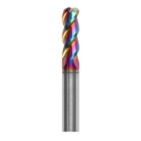
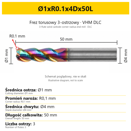
3-Flute Carbide Corner Radius End Mill for Aluminium| AL DLC
Ø1xR0.1x4Dx50L Ø1xR0.2x4Dx50L Ø1xR0.3x4Dx50L Ø1.5xR0.1x4Dx50L Ø1.5xR0.2x4Dx50L + 137 morePrice €5.89Price €4.79without VAT -
Bestseller
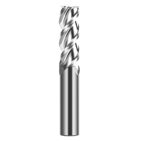
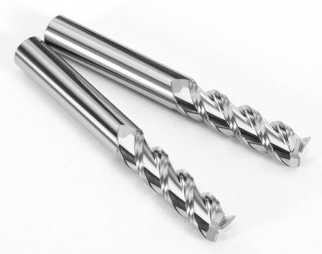 3-Flute End Mills 0.00
3-Flute Carbide End Mill VHM Z-3 for Aluminium| TriMill AL
Ø1x3xD4x50L Ø1.5x5x4Dx50L Ø2x6x4Dx50L Ø2.5x8x4Dx50L Ø3x9x3Dx50L + 41 morePrice €5.08Price €4.13without VAT -
Bestseller
 Countersinks 0.00
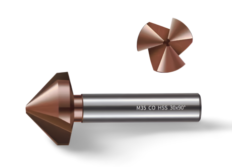
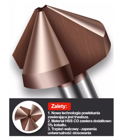
3-Flute Countersink Fi4.5-fi60, 90° - HSS-CO - 5% Kobaltu | Straight Shank
Ø4.5 x 4 x 90° x 40L Ø5 x 5 x 90° x 45L Ø6.3 x 5 x 90° x 45L Ø8.3 x 6 x 90° x 50L Ø10.4 x 6 x 90° x 50L + 12 morePrice €4.79Price €3.89without VAT -
Bestseller
 3-Flute End Mills 0.00
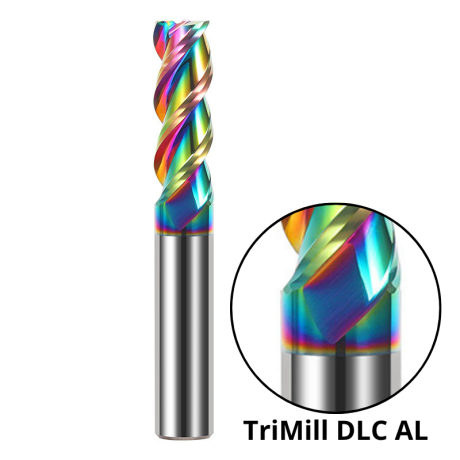
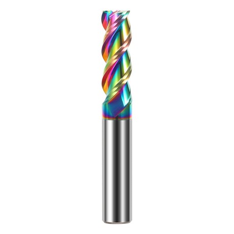
3-Flute DLC Coated Carbide End Mill | TriMill DLC AL
Ø1x3x4Dx50L Ø1.5x5x4Dx50L Ø2x6x4Dx50L Ø2.5x8x4Dx50L Ø3x8x3Dx50L + 38 morePrice €5.05Price €4.10without VAT -
Bestseller

 3-Flute End Mills 0.00
3-Flute HRC65 DLC Coated Carbide End Mill, U-Shaped Flute, for Aluminium | DuraEdge3 Alu
Ø1x3x4Dx50L Ø1.5x5x4Dx50L Ø2x6x4Dx50L Ø2.5x8x4Dx50L Ø3x9x3Dx50L + 40 morePrice €6.73Price €5.47without VAT