

MFPN66 planning head with internal cooling for inserts PNMU090508 - FMB push-on holder
Shipping costs are not included in the price.
Shipping costs are not included in the price.
Ask about the product

The administrator of personal data is Kortools. We process it to respond to your inquiry. More information regarding the processing of personal data can be found in privacy policy.
Select a product variant:
Individual variants may differ in price
Product code: 95FF-903C5
Product description
66° approach angle • internal coolant • FMB shell mounting
MFPN66 shell milling cutter for face milling and high-feed roughing. The 42CrMo steel body accepts double-sided PNMU090508 inserts with ten cutting edges per insert. The approach angle is 66°. Internal passages allow coolant to reach the cutting area through a suitable arbor and the tool.
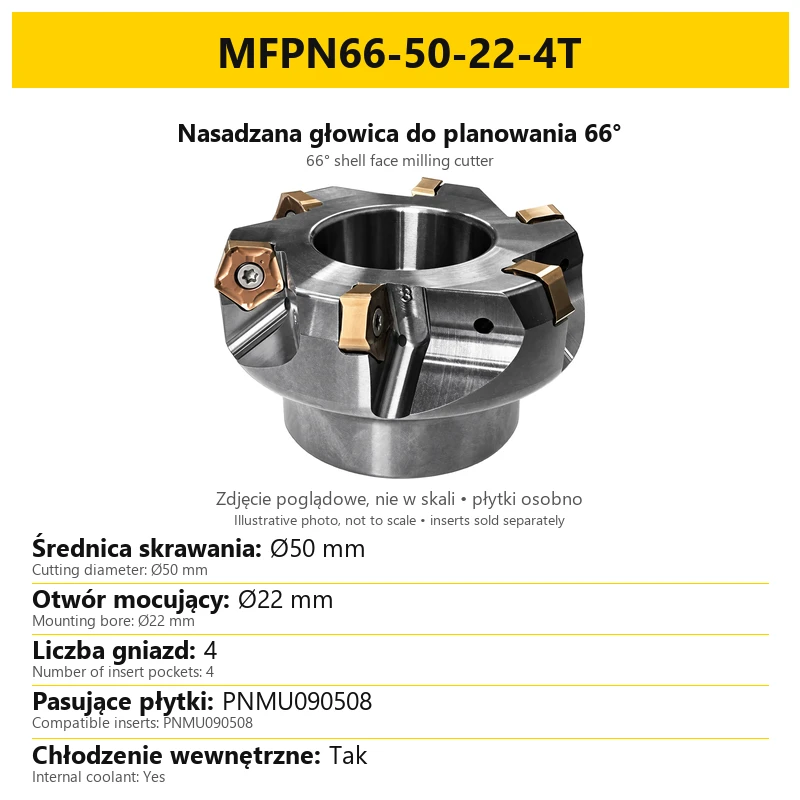
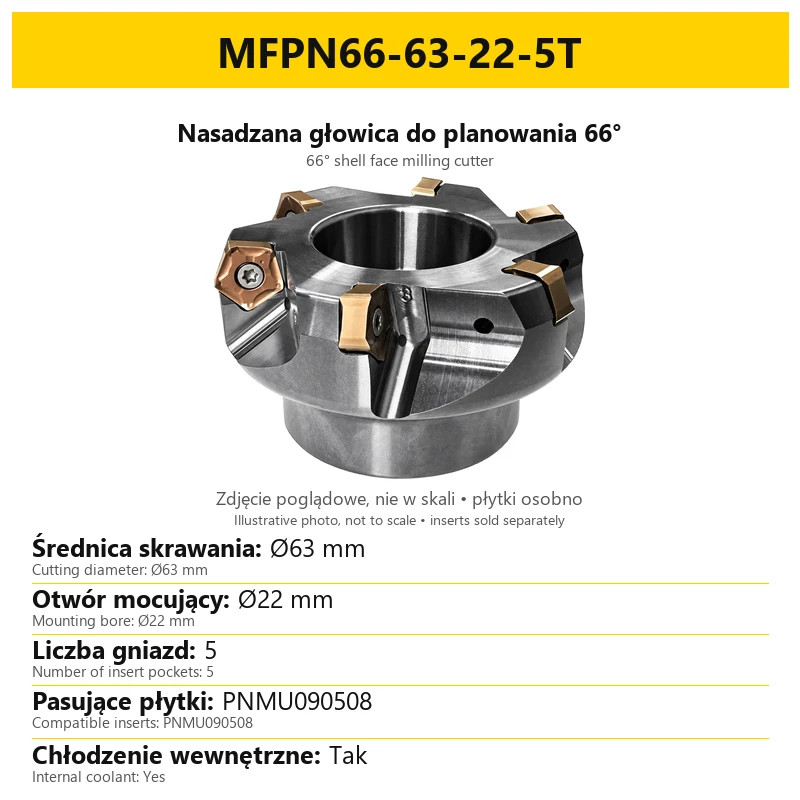
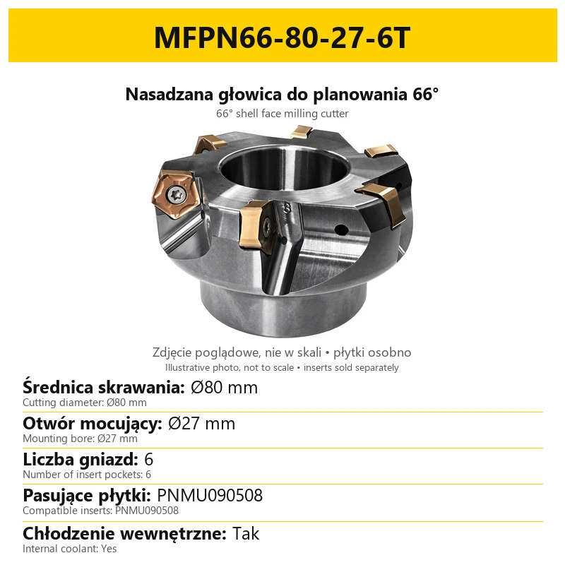
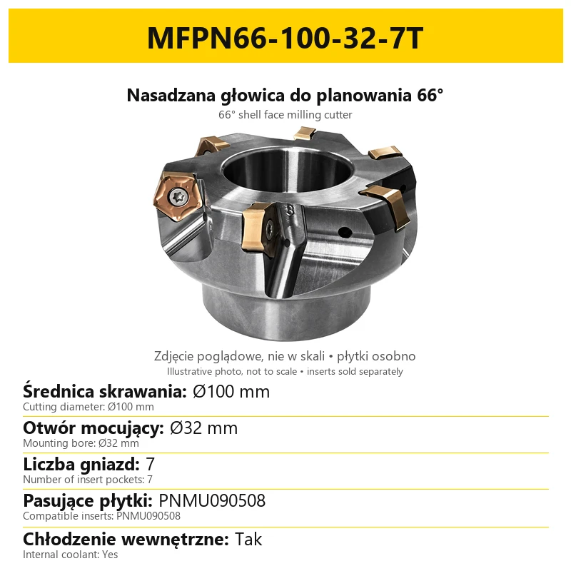
The item sold is one cutter body without cutting inserts. Inserts are selected and purchased separately. The photographs show an assembled cutter; they are illustrative and not to scale. The selected variant specifies the cutting diameter, mounting bore and number of insert pockets.
Applications and workpiece material
| Operation | Purpose and conditions |
|---|---|
| Face milling | Machining flat surfaces with a 66° approach-angle cutter. |
| Roughing | Removing stock with feed, depth and width of cut adapted to the insert and rigidity of the machining setup. |
| High-feed machining | The appropriate feed depends on insert geometry and grade, workpiece material and machine capability. |
| Plunge milling | Only under suitable, prepared machining conditions. Confirm the entry capability of the assembled tool for the planned toolpath. |
The system is used for steel, stainless steel, cast iron and selected special alloys with an appropriate insert grade. The 42CrMo body material does not identify the carbide grade or coating of the cutting insert. Select the insert for the specific workpiece material, cutting conditions and required surface quality.
Body construction and insert system
The MFPN66 body has FMB shell mounting, a central mounting bore and insert pockets distributed around its circumference. Replaceable PNMU090508 inserts are secured in the pockets by screws. After one edge wears, another available edge of the same insert can be indexed into the cutting position.
Ten cutting edges refers to one insert, not to the number of pockets or inserts in the body. The cutter has four to seven pockets, depending on diameter. The 66° angle identifies the family geometry; it is not a 90° cutter for square shoulders.
Technical specifications
| Parameter | Value / execution |
|---|---|
| Family / angle | MFPN66 / 66° |
| Body / coolant | 42CrMo / internal coolant |
| Insert system | PNMU090508; double-sided insert with 10 edges |
| Mounting / bores | FMB shell mounting; Ø22, Ø27 or Ø32 mm |
| Diameters / pockets | Ø50–Ø100 mm / 4–7 pockets, depending on variant |
| Maximum depth APMX | 5 mm |
| Screws / key | M4x10 / T15 |
| Sale unit | 1 cutter body without cutting inserts |
APMX=5 mm is the stated maximum depth of cut for this tool family. It is not a recommended depth for every operation. Choose working values to suit the insert, workpiece, spindle power, workholding and actual cutter engagement. OAL is the overall axial height of the cutter body, not the length of the cutting edge.
Dimensions and FMB mounting
| Diameter DC / pockets | Bore DCB | OAL | DCCB / KWW | Type |
|---|---|---|---|---|
| Ø50 mm / 4 | Ø22 mm | 40 mm | 17 / 10.4 mm | A |
| Ø63 mm / 5 | Ø22 mm | 40 mm | 17 / 10.4 mm | A |
| Ø80 mm / 6 | Ø27 mm | 50 mm | 34 / 12.4 mm | A |
| Ø100 mm / 7 | Ø32 mm | 50 mm | 42 / 14.4 mm | A |
DC is the cutting diameter, DCB is the mounting bore diameter and OAL is the overall axial height. DCCB and KWW are additional mounting-dimension symbols. All linear dimensions in the table are in millimetres. These executions use mounting geometry type A.
Match the FMB arbor to the cutter bore: Ø22 mm for Ø50 and Ø63, Ø27 mm for Ø80 and Ø32 mm for Ø100. Also check the mating mounting surfaces and drive keys. Cutting diameter is distinct from the mounting bore diameter. The FMB designation alone does not replace a comparison of cutter and arbor dimensions.
Coolant needs an unobstructed path through the spindle or suitable supply system, the arbor and cutter body. Passages in the cutter alone do not provide through-tool coolant when the arbor does not support the supply. Check coolant delivery to the cutting area before machining.
How to read the variant code
Example: MFPN66-63-22-5T. The code identifies the cutter family, cutting diameter, mounting bore and number of insert pockets in that order. The variant name and its card describe the same execution.
| Code element | Meaning |
|---|---|
| MFPN66 | Shell cutter family with a 66° approach angle. |
| 63 | Ø63 mm cutting diameter. |
| 22 | Ø22 mm mounting bore. |
| 5T | Five insert pockets. |
The number before T identifies the pocket count of the body. It is not the number of cutting edges available on one insert. Refer to the dimensional table for OAL and the other mounting dimensions. The code does not specify insert grade, coating or cutting parameters.
Cutting parameters and tool preparation
Example parameters for C55 steel: Vc=250 m/min, fz=0.4 mm/tooth, ap=2 mm and ae=70 mm. This is a machining example that requires adaptation to the insert and working conditions; it is not a universal setting for the entire cutter family.
| Symbol | Example value | Meaning |
|---|---|---|
| Vc | 250 m/min | Cutting speed. |
| fz | 0.4 mm/tooth | Feed per tooth, not the machine feed rate. |
| ap | 2 mm | Depth of cut in the example; below APMX 5 mm. |
| ae | 70 mm | Width of cut; this example concerns Ø80 or Ø100 cutters, not Ø50 or Ø63. |
- Select PNMU090508 insert grade and geometry for the workpiece material.
- Clean pockets and mounting surfaces before fitting inserts and the cutter.
- Check full insert seating, the condition of M4x10 screws and the T15 key fit.
- Check mounting rigidity, tool runout and coolant flow.
- Adapt feed, cutting speed, ap and ae to machine capability and perform a controlled machining trial.
Changing cutter diameter changes the relationship between cutting speed and spindle speed. Pocket count affects the machine feed rate at the same feed per tooth. Recalculate settings before transferring them to a different diameter or pocket count. For plunge milling, separately confirm insert capability and the entry toolpath.
Contents and separately selected components
| Component | Product scope |
|---|---|
| Included | 1 MFPN66 body with internal coolant, T15 key and M4x10 screws. |
| Cutting inserts | Sold separately; compatible system PNMU090508. |
| FMB arbor | Selected separately to match the mounting bore and connection geometry. |
A photograph with mounted inserts shows an assembled tool. The inserts visible in the photograph are not included with the cutter body. To begin machining, suitable inserts and an arbor compatible with the FMB connection and internal coolant supply are required.
Frequently asked questions
Are inserts included?
No. The item includes the cutter body, T15 key and M4x10 screws. PNMU090508 inserts are sold separately.
Do all variants have internal coolant?
Yes. The variants in this listing have internal coolant. A compatible supply system and arbor are needed to use it.
Does the Ø63 cutter have five or six pockets?
The internal-coolant Ø63 variant has five pockets. Follow the 5T designation in the selector.
What does ten cutting edges mean?
Ten cutting edges refers to one double-sided insert. The number of cutter pockets is given by the number before T.
Can identical settings be used for every diameter?
Adapt settings to diameter, pocket count, insert and machining conditions. The C55 example with ae=70 mm does not apply to Ø50 or Ø63 cutters.
Related products
-
CDCF-33878

 Milling Inserts 5.00
10-Edge Indexable Milling Inserts PNMU 090508 (10 pcs)
-
95FF-903C4Bestseller

 Face Milling Heads 4.43
MFPN66 planning head for inserts PNMU090508 - FMB clip-on holder


Bestsellers
-
Bestseller
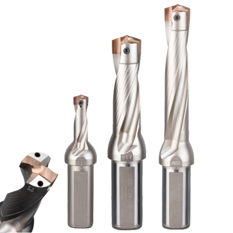
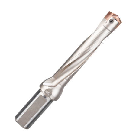
JCD modular drill with replaceable tip - internal cooling, for deep holes | GrotXD
JCD C20-100-3D Ø10~10.9 JCD C20-110-3D Ø11~11.9 JCD C20-120-3D Ø12~12.9 JCD C20-130-3D Ø13~13.9 JCD C20-140-3D Ø14~14.9 + 61 morePrice €69.86Price €56.79without VAT -
Bestseller
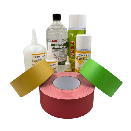
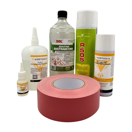
Kortools Adhesive + Tape CNC Workholding Kit
Yellow tape 5cm x 50m; adhesive 100g Yellow tape 5cm x 50m; adhesive 500g Yellow tape 10cm x 50m; adhesive 100g Yellow tape 10cm x 50m; adhesive 500g Green tape 5cm x 50m; adhesive 100g + 7 morePrice €44.66Price €36.31without VAT -
Price €17.18Price €13.97without VAT
-
Price €7.10Price €5.77without VAT
-
Price €7.56Price €6.14without VAT
-
Bestseller
 Other Accessories 0.00
CNC Chip Fan / Chip Blower
Complete CNC chip fan Kit: blades, springs, pins and screwsPrice €53.82Price €43.76without VAT -
Bestseller
 Ball Nose End Mills 0.00
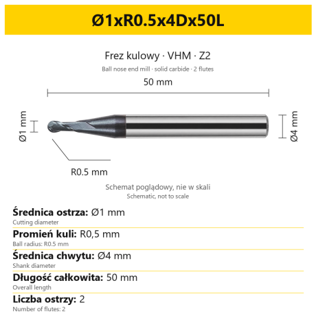
2-Flute Carbide Ball Nose End Mill - HYPERCUT
Ø1xR0.5x4Dx50L Ø1.5xR0.75x4Dx50L Ø2xR1x4Dx50L Ø2.5xR1.25x4Dx50L Ø3xR1.5x3Dx50L + 26 morePrice €10.14Price €8.25without VAT -
Bestseller
 2-Flute End Mills 0.00
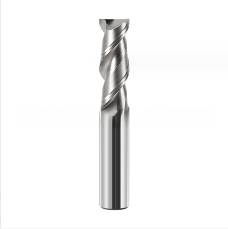
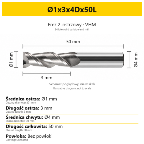
2-Flute Carbide End Mill for Aluminium
Ø1x3x4Dx50L Ø1.5x4x4Dx50L Ø2x6x4Dx50L Ø2.5x7.5x4Dx50L Ø3x9x3Dx50L + 31 morePrice €5.35Price €4.35without VAT -
Bestseller
 2-Flute End Mills 0.00
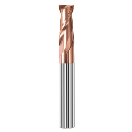
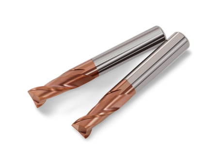
2-Flute Carbide End Mill for Steel 55 HRC - TiSiN - Solid Carbide
Ø6x24x6Dx75L Ø8x25x8Dx75L Ø4x20x4Dx100L Ø5x30x5Dx100L Ø6x30x6Dx100L + 31 morePrice €4.40Price €3.58without VAT -
Bestseller
 Ball Nose End Mills 0.00
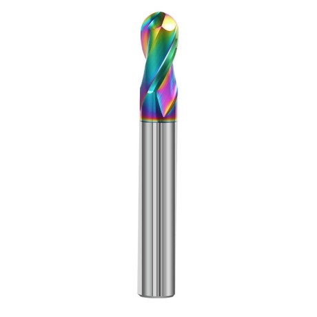
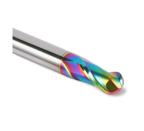
2-Flute DLC Coated Carbide Ball Nose End Mill| DuraEdge Alu
Ø1.0xR0.5x4Dx50L Ø1.5xR0.75x4Dx50L Ø2.0xR1x4Dx50L Ø2.5xR1.25x4Dx50L Ø3.0xR1.5x3Dx50L + 34 morePrice €7.89Price €6.41without VAT -
Bestseller
 2-Flute End Mills 0.00
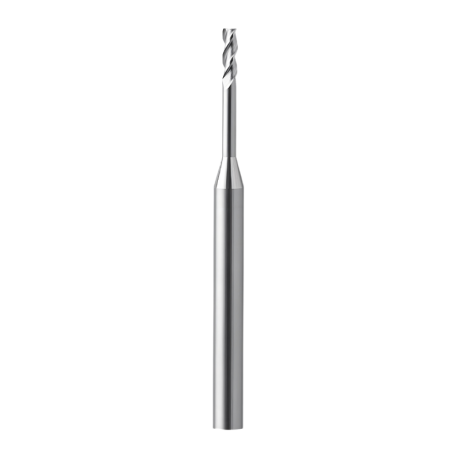
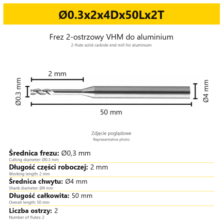
2-Flute End Mill for Aluminium | VHM | Miniature Ø0.3 - Ø0.9
Ø0.3x2x4Dx50Lx2T Ø0.3x3x4Dx50Lx2T Ø0.3x4x4Dx50Lx2T Ø0.4x2x4Dx50Lx2T Ø0.4x3x4Dx50Lx2T + 28 morePrice €7.99Price €6.50without VAT -
Bestseller
 Ball Nose End Mills 0.00
2-Flute TiSiN Coated Carbide Ball Nose End Mill
Ø1xR0.5x4Dx50L Ø1.5xR0.75x4Dx50L Ø2xR1x4Dx50L Ø2.5xR1.25x4Dx50L Ø3xR1.5x3Dx50L + 38 morePrice €7.28Price €5.92without VAT -
Bestseller
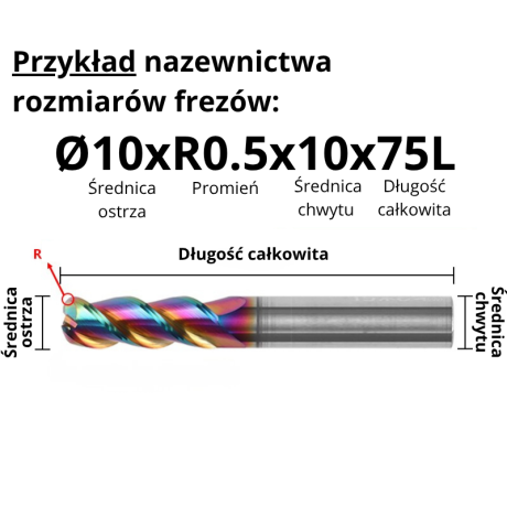
3-Flute Carbide Corner Radius End Mill for Aluminium| AL DLC
Ø1xR0.1x4Dx50L Ø1xR0.2x4Dx50L Ø1xR0.3x4Dx50L Ø1.5xR0.1x4Dx50L Ø1.5xR0.2x4Dx50L + 137 morePrice €4.96Price €4.04without VAT -
Bestseller
 3-Flute End Mills 0.00
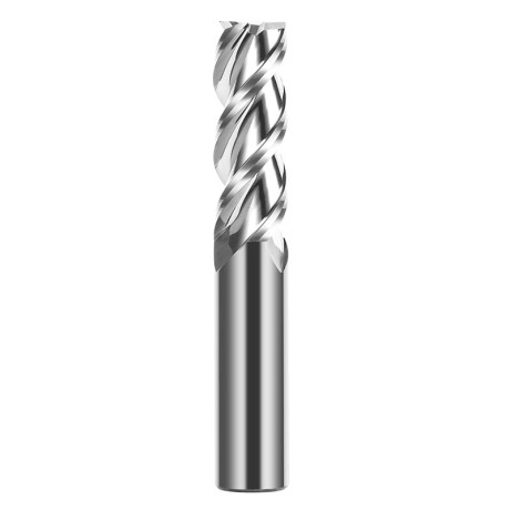
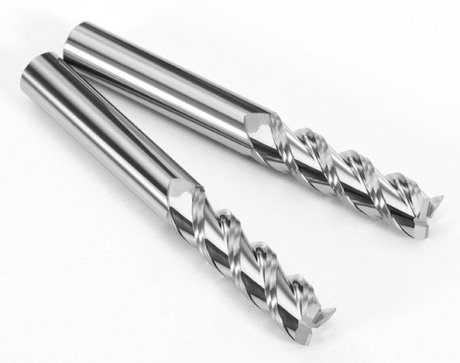
3-Flute Carbide End Mill VHM Z-3 for Aluminium| TriMill AL
Ø1x3xD4x50L Ø1.5x5x4Dx50L Ø2x6x4Dx50L Ø2.5x8x4Dx50L Ø3x9x3Dx50L + 41 morePrice €5.10Price €4.15without VAT -
Bestseller
 Countersinks 0.00
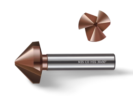
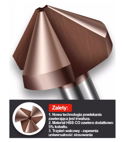
3-Flute Countersink Fi4.5-fi60, 90° - HSS-CO - 5% Kobaltu | Straight Shank
Ø4.5 x 4 x 90° x 40L Ø5 x 5 x 90° x 45L Ø6.3 x 5 x 90° x 45L Ø8.3 x 6 x 90° x 50L Ø10.4 x 6 x 90° x 50L + 12 morePrice €4.81Price €3.91without VAT -
Bestseller
 3-Flute End Mills 0.00
3-Flute DLC Coated Carbide End Mill | TriMill DLC AL
Ø1x3x4Dx50L Ø1.5x5x4Dx50L Ø2x6x4Dx50L Ø2.5x8x4Dx50L Ø3x8x3Dx50L + 38 morePrice €5.07Price €4.12without VAT