





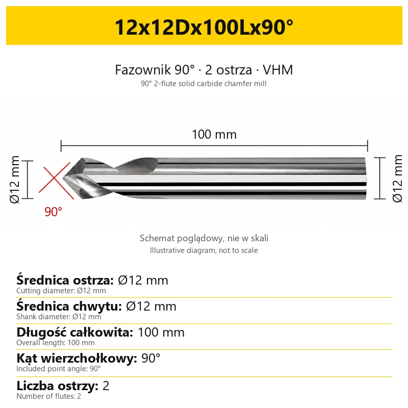


Chamfer 90° VHM Carbide Center 2 flutes For Aluminum, Plastic, Brass
Shipping costs are not included in the price.
Shipping costs are not included in the price.
Ask about the product

The administrator of personal data is Kortools. We process it to respond to your inquiry. More information regarding the processing of personal data can be found in privacy policy.
Select a product variant:
Individual variants may differ in price
Product code: FEB8-16964
Product description
90° solid carbide 2-flute chamfer mill — for aluminium, brass and plastics
Edge chamfering, deburring and spot drilling · diameters Ø1–20 mm
This solid carbide chamfer mill with a 90° included point angle is intended for edge machining in aluminium, copper, brass and plastics. Its two cutting edges are used for chamfering and deburring, while the conical tip can also produce a shallow spot to locate a hole.
Choose the size to match the shank diameter, required cutting diameter and access to the workpiece. The range includes tools with overall lengths of 50, 60 or 75 mm, plus selected sizes with a 100 mm overall length. Images illustrate the geometry; the dimensions of each tool are stated on its size card.
1. Construction and technical specifications
The tool is made from solid carbide, also designated VHM. The cutting section has two flutes and a conical 90° tip. Clamp the cylindrical shank in a holder matched to its actual diameter.
| Parameter | Value |
|---|---|
| Tool material | VHM — solid carbide |
| Grain size | 0.6 µm |
| Number of flutes | 2 |
| Included point angle | 90° |
| Cutting diameter d | Ø1–20 mm, depending on the variant |
| Overall length L | 50, 60, 75 or 100 mm, depending on the variant |
The cutting diameter describes the cutting section, not the width of the finished chamfer. The resulting chamfer also depends on the tool position and depth of engagement. Overall length is neither flute length nor the permitted machining depth.
2. Workpiece materials
This version is primarily intended for non-ferrous metals and plastics. Carry out a trial cut in the actual material grade: alloy composition, material condition and susceptibility to deformation affect the finished edge.
| Material | Application |
|---|---|
| Aluminium | Chamfering edges and removing burrs left by previous machining operations. |
| Copper | Finishing edges with adequate chip evacuation. |
| Brass | Chamfering accessible edges and machining hole rims. |
| Plastics | Chamfering and deburring; adapt cutting conditions to the specific plastic. |
When machining plastics, monitor heat, deformation and material build-up. In non-ferrous metals, check that chips leave the cutting zone instead of being recut. A two-flute design does not replace correct clamping, feed selection and suitable coolant or air supply.
3. Chamfering, deburring and spot drilling
The same tool can support several finishing operations, but each requires a suitable toolpath and access to the surface. Before machining, check clearance between the holder, shank, workpiece and fixture.
| Operation | Use |
|---|---|
| Chamfering | Producing a bevel on an accessible workpiece edge or hole rim; chamfer width is set by tool position and engagement depth. |
| Deburring | Removing burrs after milling or drilling, within the limits imposed by access and edge geometry. |
| Spot drilling | Producing a shallow spot to locate a hole, where a 90° angle is suitable for the subsequent operation and drill. |
For spot drilling, consider the geometry of the drill used in the next operation. A 90° spot is not automatically suitable for every drill, particularly a carbide drill. Do not use the chamfer mill as a substitute for a drill when producing a full-depth hole.
4. Reading the size designation
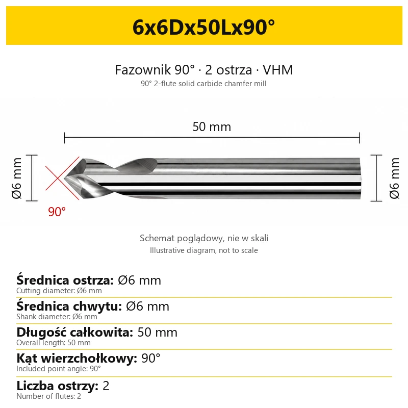
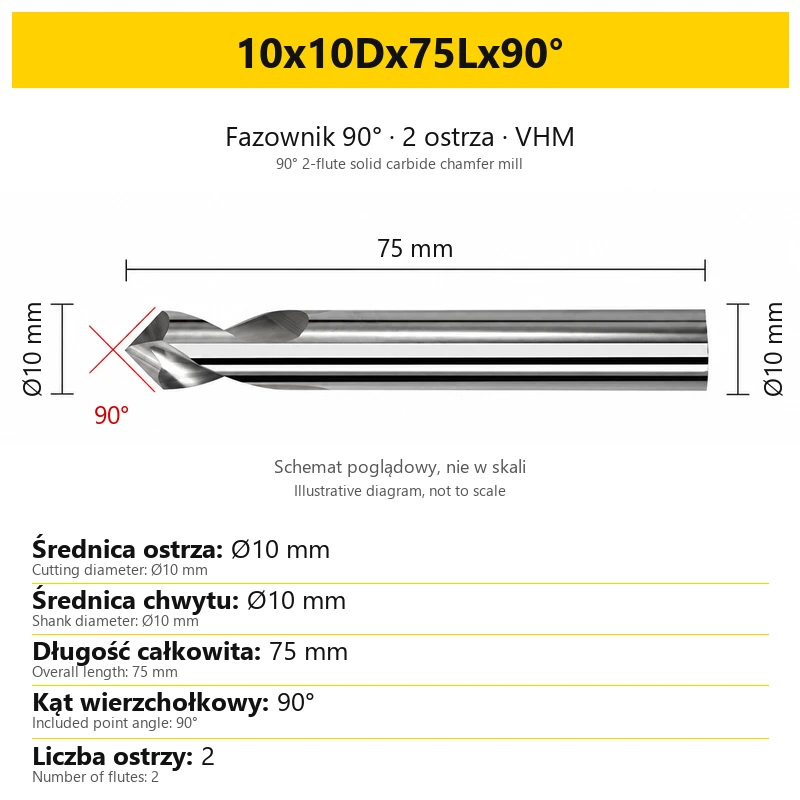
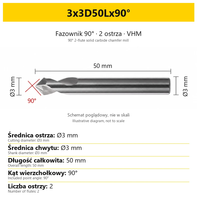
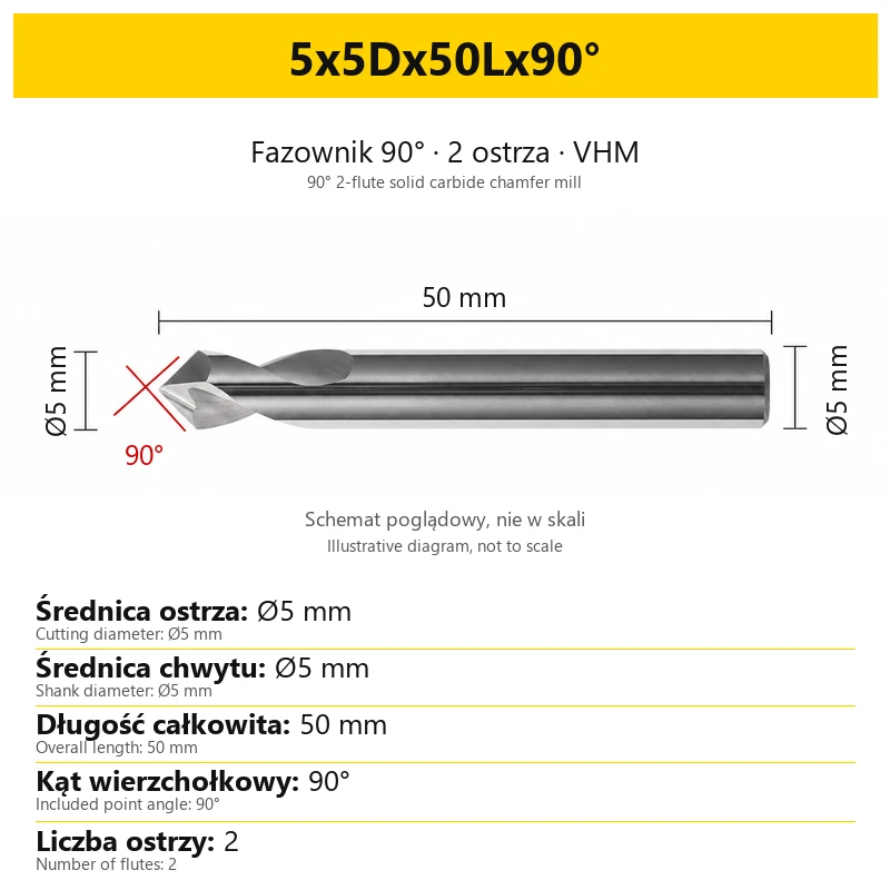
The designation 4x4Dx50Lx90° describes a 4 mm cutting diameter, 4 mm shank diameter, 50 mm overall length and 90° included point angle. D and L refer to different dimensions; check both when selecting the tool and holder.
| Designation element | Meaning |
|---|---|
| First number — d | Cutting diameter, in millimetres. |
| Number before D | Diameter of the shank clamped in the holder, in millimetres. |
| Number before L | Overall tool length, in millimetres. |
| 90° | Full included point angle of the cutting section. |
Within this range, the shank diameter matches the cutting diameter. The Ø1 variant has a Ø1 mm shank and the Ø2 variant has a Ø2 mm shank. Check the collet clamping range carefully, especially for these small sizes; it must match the chosen tool.
5. Available variants and length selection
The table groups the variants by overall length. All have two flutes and a 90° included point angle. Cutting diameter d and shank diameter D are equal for every size listed.
| Overall length L | Cutting diameter d and shank diameter D |
|---|---|
| 50 mm | Ø1, Ø2, Ø3, Ø4, Ø5, Ø6 mm |
| 60 mm | Ø8 mm |
| 75 mm | Ø10, Ø12 mm |
| 100 mm | Ø4, Ø6, Ø8, Ø10, Ø12, Ø16, Ø20 mm |
Choose the shortest tool and smallest overhang that allow safe access to the edge. A 100 mm tool may provide the required reach, but the entire overall length is not a cutting section.
Before ordering, compare the size with the required access, available holder clearance and clamping range. A larger tool diameter does not require a wider chamfer: the machining setup determines the finished chamfer dimensions.
6. Clamping and starting the operation
- Match the holder to the shank. Clean the shank, collet and clamping surfaces. Check the cutting edges and ensure that the tool is seated correctly.
- Keep overhang short. Extend the tool only as far as the operation requires, following the holder requirements. Do not clamp the cutting section.
- Use a stable setup. Clamp the workpiece securely and check runout. This tool requires controlled machining conditions; do not select it for a handheld drill or a low-speed drill press.
- Make a trial pass. Begin with light engagement, inspect the chamfer and adjust the tool position. Set cutting conditions for the actual material, engaged diameter and rigidity of the setup.
- Monitor chips and finish. Provide chip evacuation and coolant or air appropriate to the workpiece material. If vibration, an uneven chamfer or material build-up occurs, stop machining and investigate the cause.
Cutting speed varies along the cone with the diameter at which the cutting edge is engaged. Spindle speed and feed therefore cannot be selected solely from the nominal shank diameter. Assess cutting conditions separately for longer overhangs instead of directly copying settings from a shorter tool.
7. Selecting the product and scope of supply
Choose one size in the variant selector. The offer is for one chamfer mill in the selected size; the list of available diameters does not represent a set containing every tool.
The size card states d, D, L, included point angle and number of flutes. Its diagram is illustrative and must not be used to measure tool proportions on screen. Before confirming your selection, compare the stated dimensions with your holder and operation requirements.
8. Frequently asked questions
Does a 90° chamfer mill produce a 45° chamfer?
Yes, with the appropriate orientation of the tool axis to the surface. The 90° value is the full cone angle; chamfer width and position depend on the programmed toolpath and engagement depth.
Does a 100 mm length mean a 100 mm cutting section?
No. This is the overall length, including the shank. When assessing access to an edge, also allow for the holder, overhang and position of the cutting section.
Do the Ø1 and Ø2 variants have a Ø4 mm shank?
No. In this range, the Ø1 variant has a Ø1 mm shank and the Ø2 variant has a Ø2 mm shank. Your collet must accommodate the selected diameter within its permitted clamping range.
Can the tool be used for spot drilling?
It can produce a shallow spot where a 90° angle is appropriate for the operation. Selection before subsequent drilling also depends on the geometry and material of the drill.
Is this tool primarily intended for steel?
This version is primarily intended for aluminium, copper, brass and plastics. For regular steel machining, select a tool intended for the particular material grade and operation.
Do two cutting edges guarantee a burr-free result?
The result also depends on the workpiece material, edge condition, clamping, chip evacuation and cutting parameters. Inspect the finished edge after a trial pass and adjust the process where necessary.
Bestsellers
-
Bestseller
JCD modular drill with replaceable tip - internal cooling, for deep holes | GrotXD
JCD C20-100-3D Ø10~10.9 JCD C20-110-3D Ø11~11.9 JCD C20-120-3D Ø12~12.9 JCD C20-130-3D Ø13~13.9 JCD C20-140-3D Ø14~14.9 + 61 morePrice €69.86Price €56.79without VAT -
Bestseller
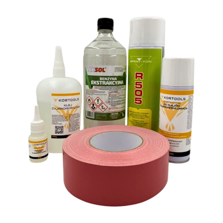
Kortools Adhesive + Tape CNC Workholding Kit
Yellow tape 5cm x 50m; adhesive 100g Yellow tape 5cm x 50m; adhesive 500g Yellow tape 10cm x 50m; adhesive 100g Yellow tape 10cm x 50m; adhesive 500g Green tape 5cm x 50m; adhesive 100g + 7 morePrice €44.66Price €36.31without VAT -
Price €17.18Price €13.97without VAT
-
Price €7.10Price €5.77without VAT
-
Price €7.56Price €6.14without VAT
-
Bestseller
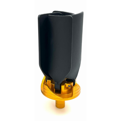
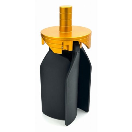 Other Accessories 0.00
CNC Chip Fan / Chip Blower
Complete CNC chip fan Kit: blades, springs, pins and screwsPrice €53.82Price €43.76without VAT -
Bestseller
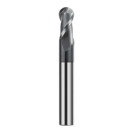
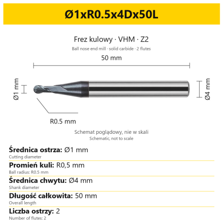 Ball Nose End Mills 0.00
2-Flute Carbide Ball Nose End Mill - HYPERCUT
Ø1xR0.5x4Dx50L Ø1.5xR0.75x4Dx50L Ø2xR1x4Dx50L Ø2.5xR1.25x4Dx50L Ø3xR1.5x3Dx50L + 26 morePrice €10.14Price €8.25without VAT -
Bestseller
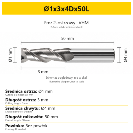 2-Flute End Mills 0.00
2-Flute Carbide End Mill for Aluminium
Ø1x3x4Dx50L Ø1.5x4x4Dx50L Ø2x6x4Dx50L Ø2.5x7.5x4Dx50L Ø3x9x3Dx50L + 31 morePrice €5.35Price €4.35without VAT -
Bestseller
 2-Flute End Mills 0.00
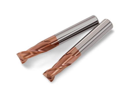
2-Flute Carbide End Mill for Steel 55 HRC - TiSiN - Solid Carbide
Ø6x24x6Dx75L Ø8x25x8Dx75L Ø4x20x4Dx100L Ø5x30x5Dx100L Ø6x30x6Dx100L + 31 morePrice €4.40Price €3.58without VAT -
Bestseller
 Ball Nose End Mills 0.00
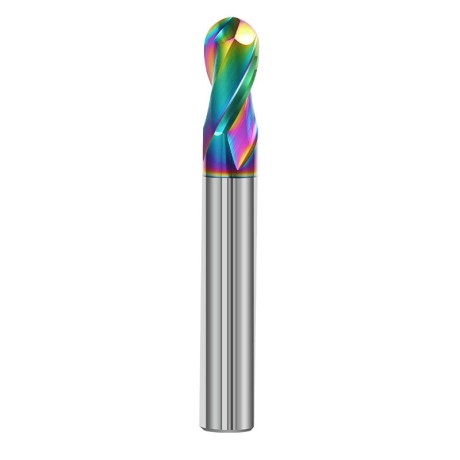
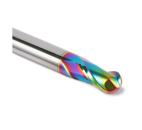
2-Flute DLC Coated Carbide Ball Nose End Mill| DuraEdge Alu
Ø1.0xR0.5x4Dx50L Ø1.5xR0.75x4Dx50L Ø2.0xR1x4Dx50L Ø2.5xR1.25x4Dx50L Ø3.0xR1.5x3Dx50L + 34 morePrice €7.89Price €6.41without VAT -
Bestseller
 2-Flute End Mills 0.00
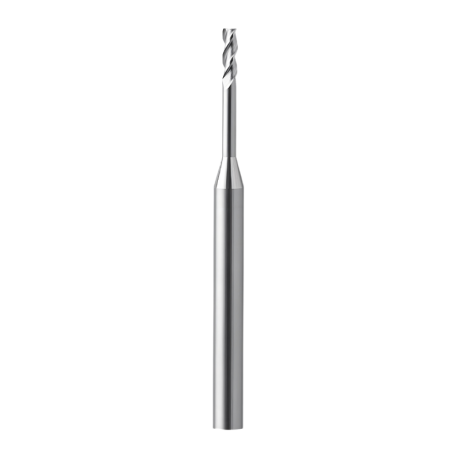
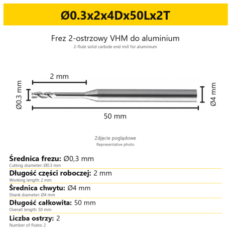
2-Flute End Mill for Aluminium | VHM | Miniature Ø0.3 - Ø0.9
Ø0.3x2x4Dx50Lx2T Ø0.3x3x4Dx50Lx2T Ø0.3x4x4Dx50Lx2T Ø0.4x2x4Dx50Lx2T Ø0.4x3x4Dx50Lx2T + 28 morePrice €7.99Price €6.50without VAT -
Bestseller
 Ball Nose End Mills 0.00
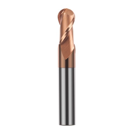
2-Flute TiSiN Coated Carbide Ball Nose End Mill
Ø1xR0.5x4Dx50L Ø1.5xR0.75x4Dx50L Ø2xR1x4Dx50L Ø2.5xR1.25x4Dx50L Ø3xR1.5x3Dx50L + 38 morePrice €7.28Price €5.92without VAT -
Bestseller
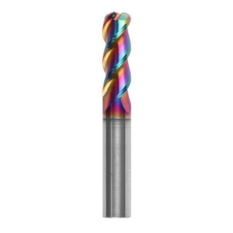
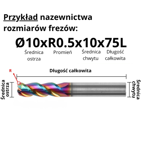
3-Flute Carbide Corner Radius End Mill for Aluminium| AL DLC
Ø1xR0.1x4Dx50L Ø1xR0.2x4Dx50L Ø1xR0.3x4Dx50L Ø1.5xR0.1x4Dx50L Ø1.5xR0.2x4Dx50L + 137 morePrice €4.96Price €4.04without VAT -
Bestseller
 3-Flute End Mills 0.00
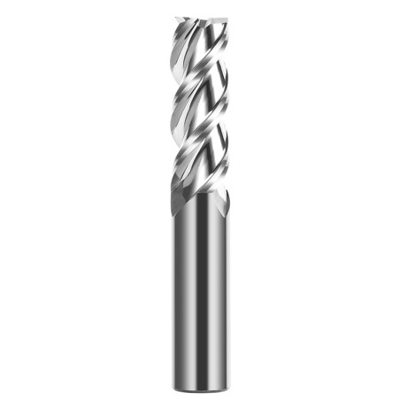
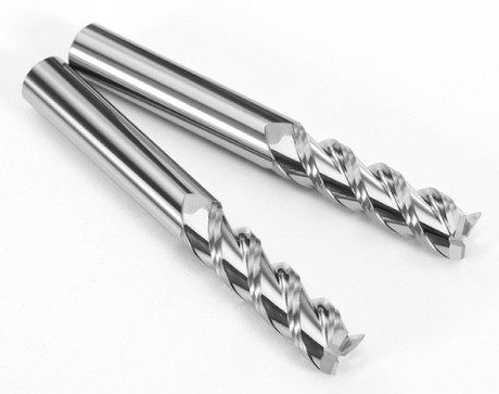
3-Flute Carbide End Mill VHM Z-3 for Aluminium| TriMill AL
Ø1x3xD4x50L Ø1.5x5x4Dx50L Ø2x6x4Dx50L Ø2.5x8x4Dx50L Ø3x9x3Dx50L + 41 morePrice €5.10Price €4.15without VAT -
Bestseller
 Countersinks 0.00
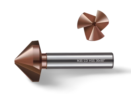
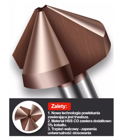
3-Flute Countersink Fi4.5-fi60, 90° - HSS-CO - 5% Kobaltu | Straight Shank
Ø4.5 x 4 x 90° x 40L Ø5 x 5 x 90° x 45L Ø6.3 x 5 x 90° x 45L Ø8.3 x 6 x 90° x 50L Ø10.4 x 6 x 90° x 50L + 12 morePrice €4.81Price €3.91without VAT -
Bestseller
 3-Flute End Mills 0.00
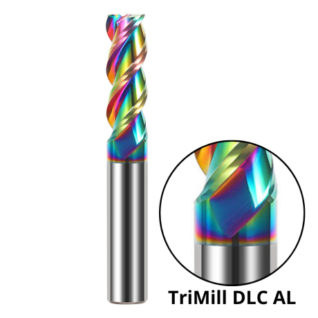
3-Flute DLC Coated Carbide End Mill | TriMill DLC AL
Ø1x3x4Dx50L Ø1.5x5x4Dx50L Ø2x6x4Dx50L Ø2.5x8x4Dx50L Ø3x8x3Dx50L + 38 morePrice €5.07Price €4.12without VAT