

EWN precision boring bar, diameter 20-510mm
Shipping costs are not included in the price.
Shipping costs are not included in the price.

Weekly deals
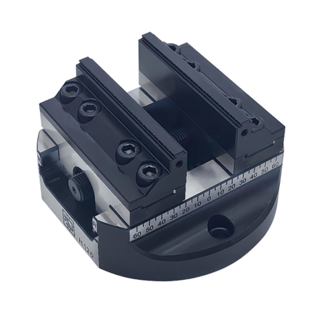
5-axis vise with hard jaws
Self-centering machine vise. Hard jaws included.
excl. VAT
Regular price:
Lowest price in the 30 days before the reduction:
Time left
Offer ends 06.11.2026 23:59. Offer applies to the vise + hard jaws bundle only.
Ask about the product

The administrator of personal data is Kortools. We process it to respond to your inquiry. More information regarding the processing of personal data can be found in privacy policy.
Select a product variant:
Individual variants may differ in price
Product code: 13A1-71366
Product description
SMS EWN fine boring heads — 20–510 mm
LBK heads · BST bridge boring heads · ENH insert holders
The SMS EWN system includes adjustable fine boring heads and replaceable ENH insert holders. The working range depends on the selected head and holder. BST bridge heads have separate ranges for internal boring and external turning.
1. System components and applications
| Component | Application |
|---|---|
| SMS EWN / LBK | Fine boring with diameter micro-adjustment; forward and back-boring ranges depend on the holder. |
| BST | Bridge heads for large bores and external diameters within the ranges listed below. |
| ENH | Replaceable insert holders. An ENH option is the holder alone, without a head or cutting insert. |
The heads have steel bodies with an adjustment mechanism and a setting lock. The insert is a separate cutting component. Select the head, holder and insert family together.
2. LBK head specifications
| Head | Range [mm] | Interface | Working L [mm] | Insert |
|---|---|---|---|---|
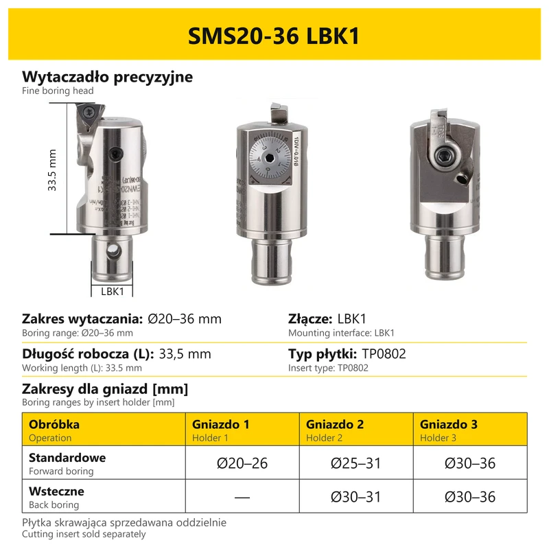
| SMS20-36 | 20–36 | LBK1 | 33.5 | TP0802 |
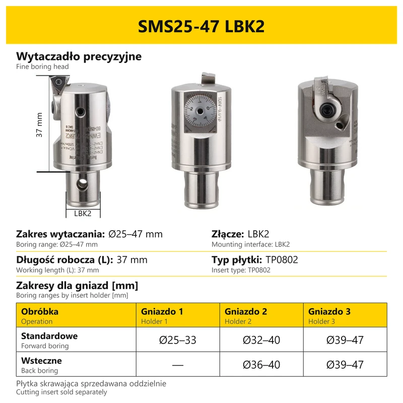
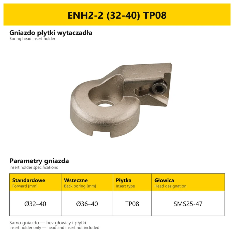
| SMS25-47 | 25–47 | LBK2 | 37 | TP0802 |
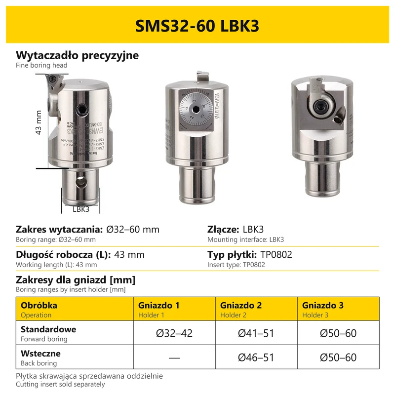
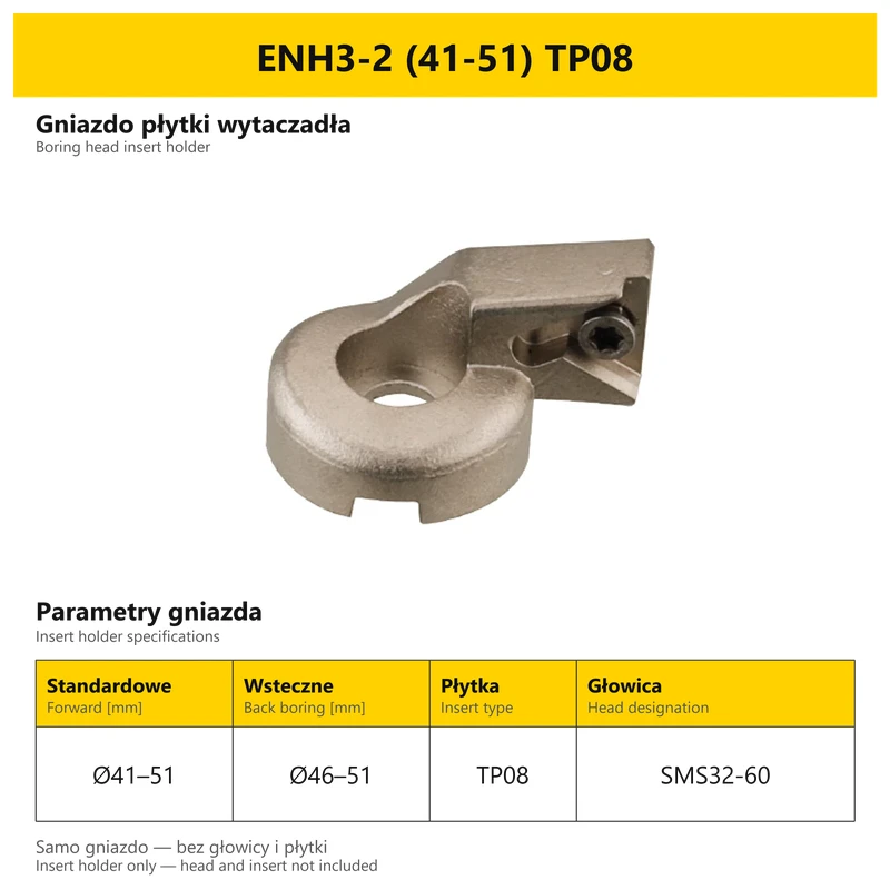
| SMS32-60 | 32–60 | LBK3 | 43 | TP0802 |
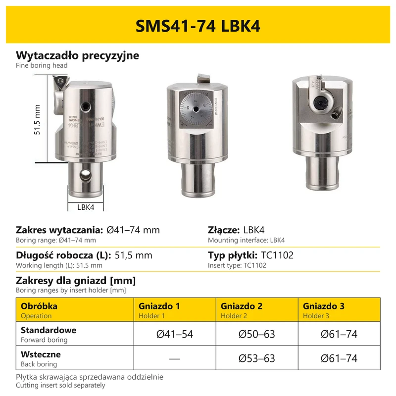
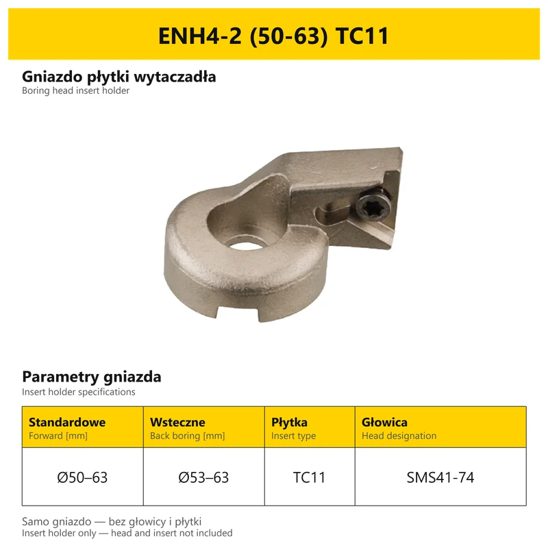
| SMS41-74 | 41–74 | LBK4 | 51.5 | TC1102 |
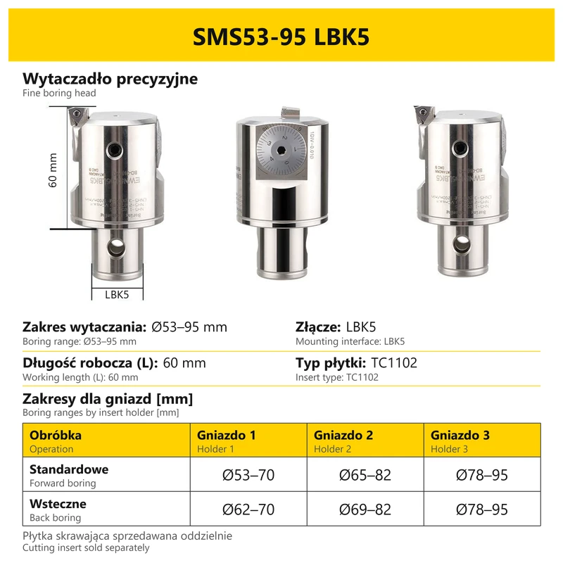
| SMS53-95 | 53–95 | LBK5 | 60 | TC1102 |
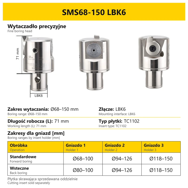
| SMS68-150 | 68–150 | LBK6 | 71 | TC1102 |
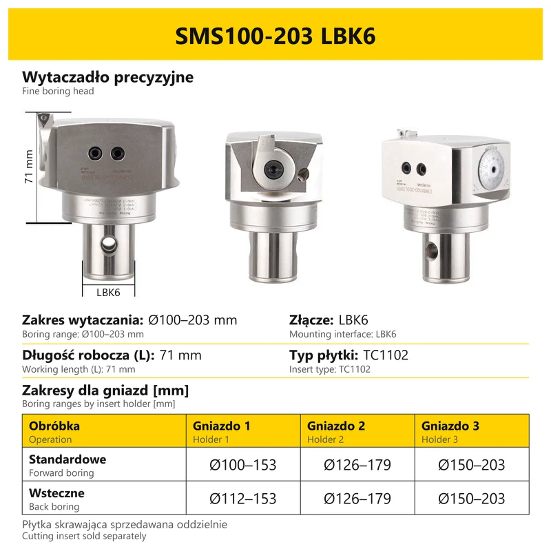
| SMS100-203 | 100–203 | LBK6 | 71 | TC1102 |
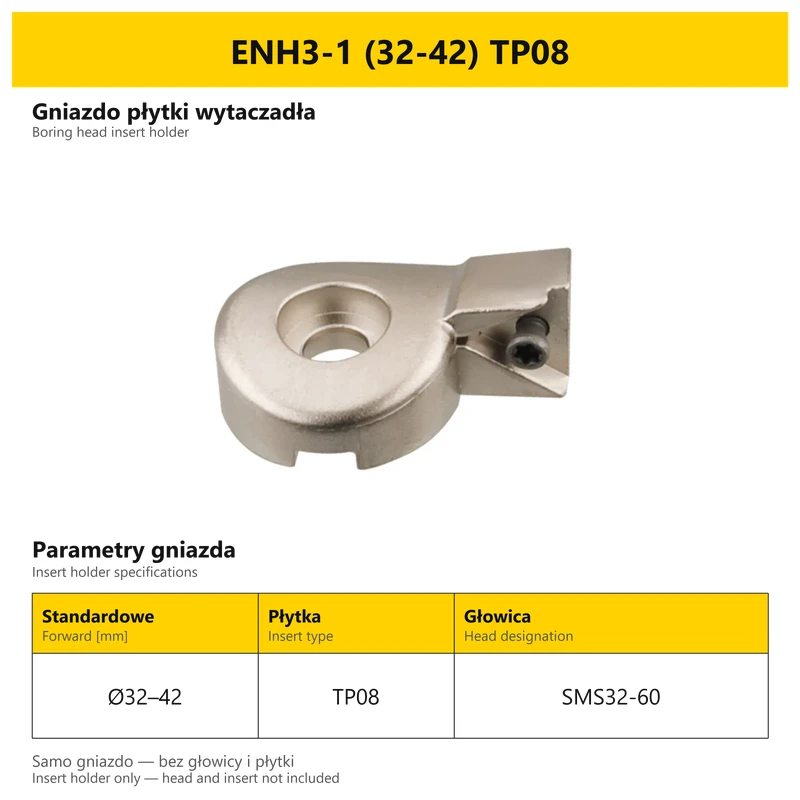
L refers to the working section marked by dimension lines on the head card. The LBK interface is listed separately. A holder number in the range table identifies a configuration of that particular head, not universal compatibility with every ENH holder carrying the same final number.
3. Complete ranges for holders 1, 2 and 3
| Head | Operation | Holder 1 [mm] | Holder 2 [mm] | Holder 3 [mm] |
|---|---|---|---|---|
| SMS20-36 | Forward | 20–26 | 25–31 | 30–36 |
| SMS20-36 | Back | — | 30–31 | 30–36 |
| SMS25-47 | Forward | 25–33 | 32–40 | 39–47 |
| SMS25-47 | Back | — | 36–40 | 39–47 |
| SMS32-60 | Forward | 32–42 | 41–51 | 50–60 |
| SMS32-60 | Back | — | 46–51 | 50–60 |
| SMS41-74 | Forward | 41–54 | 50–63 | 61–74 |
| SMS41-74 | Back | — | 53–63 | 61–74 |
| SMS53-95 | Forward | 53–70 | 65–82 | 78–95 |
| SMS53-95 | Back | 62–70 | 69–82 | 78–95 |
| SMS68-150 | Forward | 68–100 | 94–126 | 118–150 |
| SMS68-150 | Back | 80–100 | 94–126 | 118–150 |
| SMS100-203 | Forward | 100–153 | 126–179 | 150–203 |
| SMS100-203 | Back | 112–153 | 126–179 | 150–203 |
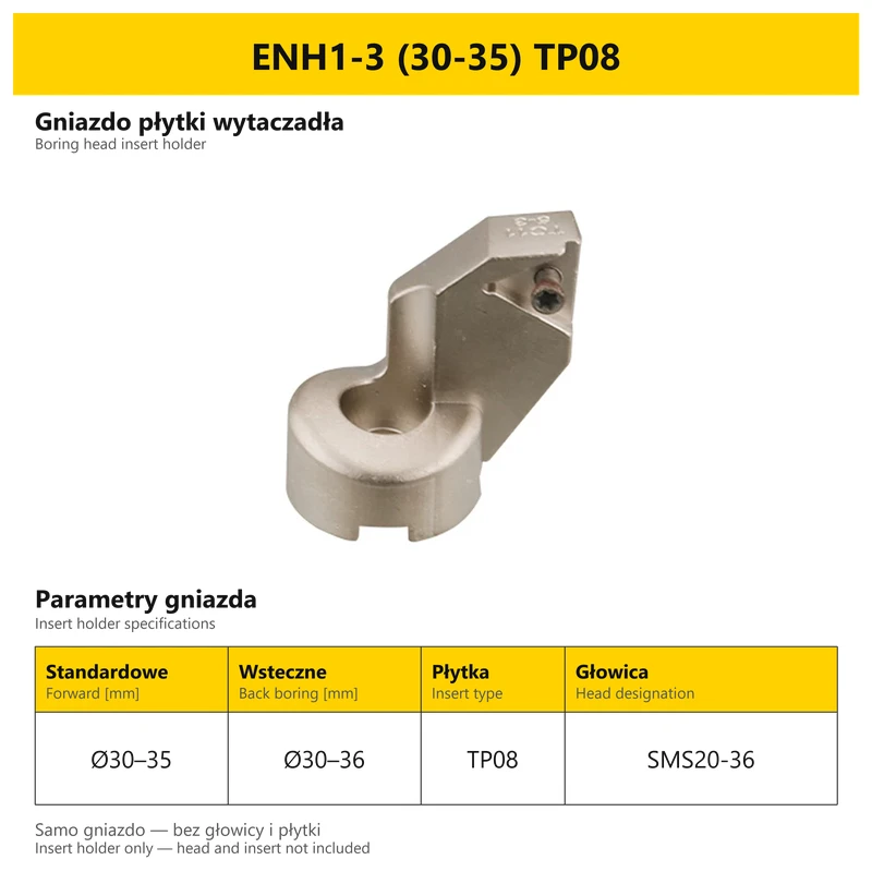
All ranges are diameters in millimetres. A dash indicates no back-boring range for that configuration in this table. SMS53–95 remains a head with a maximum range of 95 mm. When selecting a separate holder, also check its own card: ENH1-3 (30–35) TP08 has a forward range of 30–35 mm and a back-boring range of 30–36 mm; these are not replaced by the overall head range.
4. BST bridge boring heads
| Internal boring [mm] | External turning [mm] | Interface | Overall height [mm] | Cutting-head height [mm] | Insert |
|---|---|---|---|---|---|
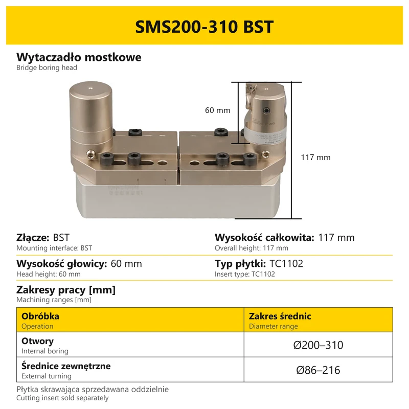
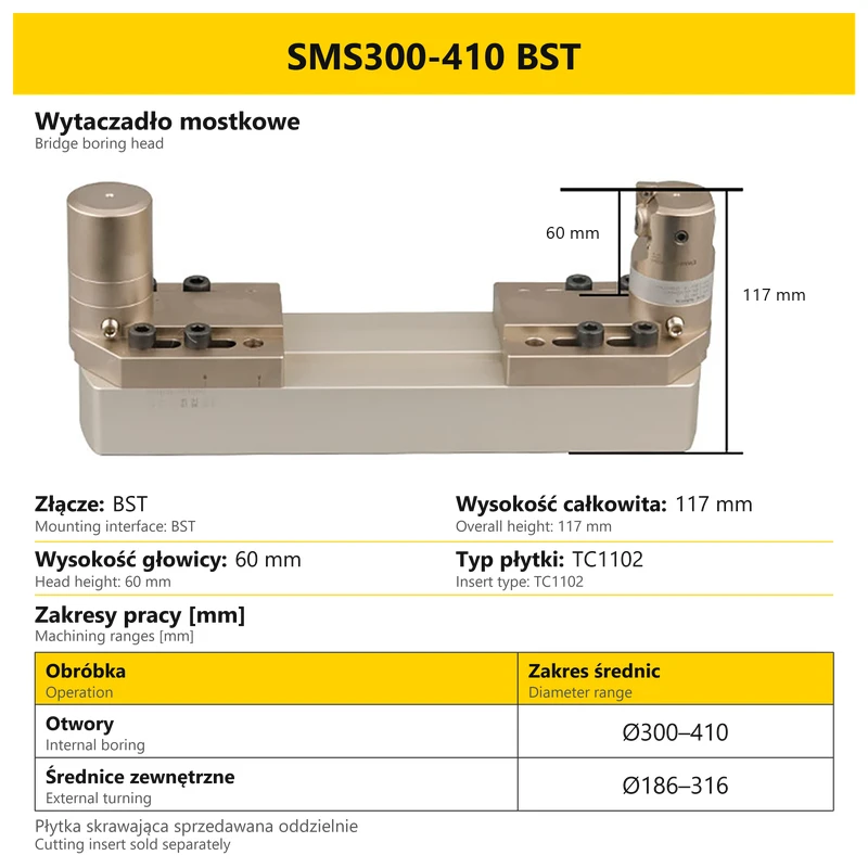
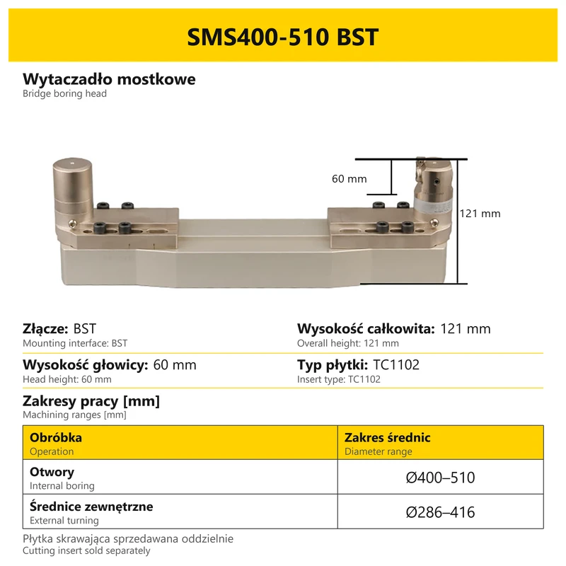
| 200–310 | 86–216 | BST | 117 | 60 | TC1102 |
| 300–410 | 186–316 | BST | 117 | 60 | TC1102 |
| 400–510 | 286–416 | BST | 121 | 60 | TC1102 |
External turning and back boring are different operations. For bridge heads, use either the internal-boring or external-turning range above, according to the operation. The BST toolholder is selected separately.
5. Ranges of separate ENH holders
| Holder | Head designation | Forward [mm] | Back [mm] | Insert version |
|---|---|---|---|---|
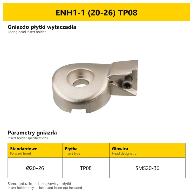
| ENH1-1 | SMS20-36 | 20–26 | — | TP08 |
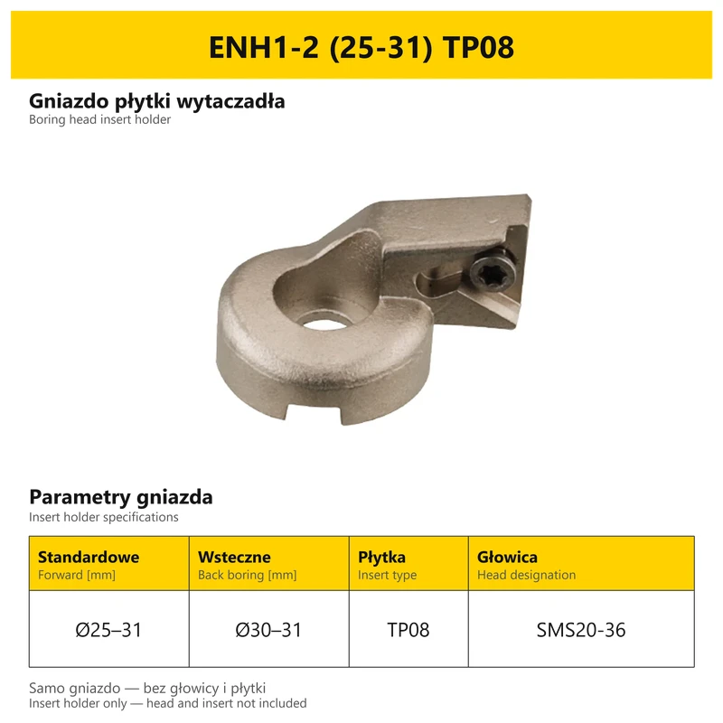
| ENH1-2 | SMS20-36 | 25–31 | 30–31 | TP08 |
| ENH1-3 | SMS20-36 | 30–35 | 30–36 | TP08 |
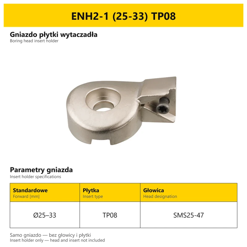
| ENH2-1 | SMS25-47 | 25–33 | — | TP08 |
| ENH2-2 | SMS25-47 | 32–40 | 36–40 | TP08 |
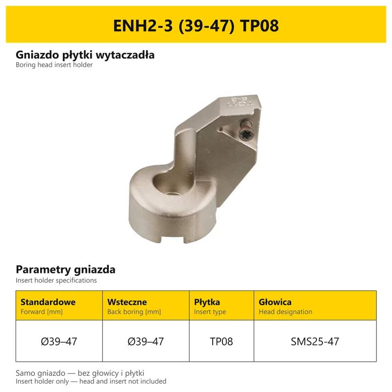
| ENH2-3 | SMS25-47 | 39–47 | 39–47 | TP08 |
| ENH3-1 | SMS32-60 | 32–42 | — | TP08 |
| ENH3-2 | SMS32-60 | 41–51 | 46–51 | TP08 |
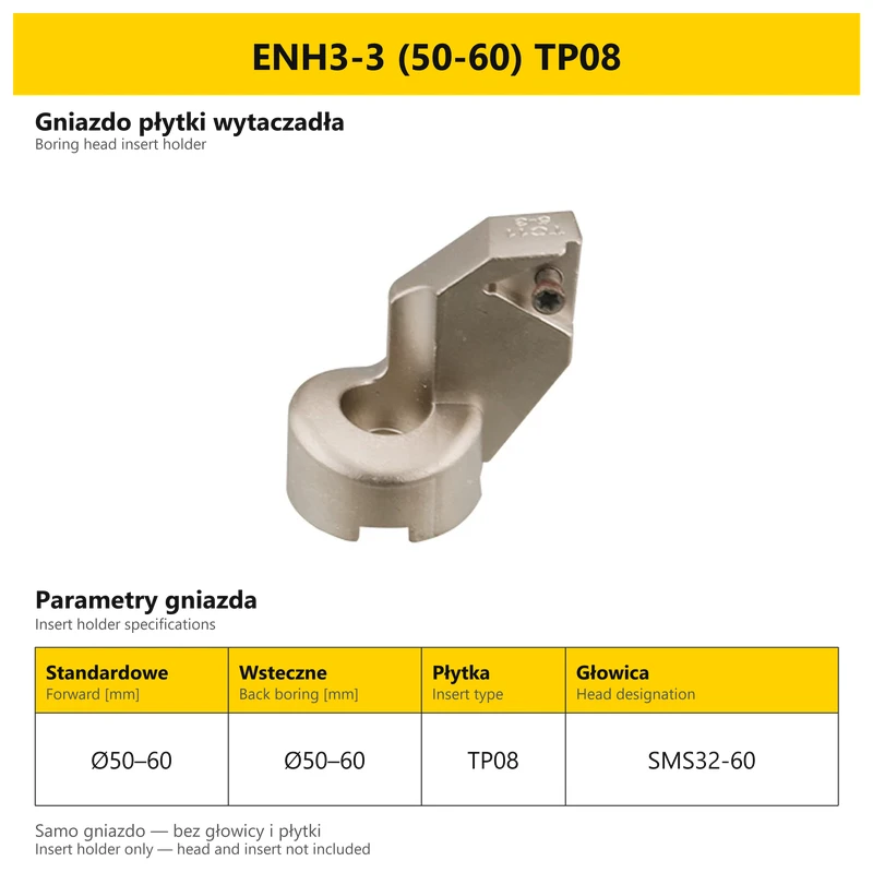
| ENH3-3 | SMS32-60 | 50–60 | 50–60 | TP08 |
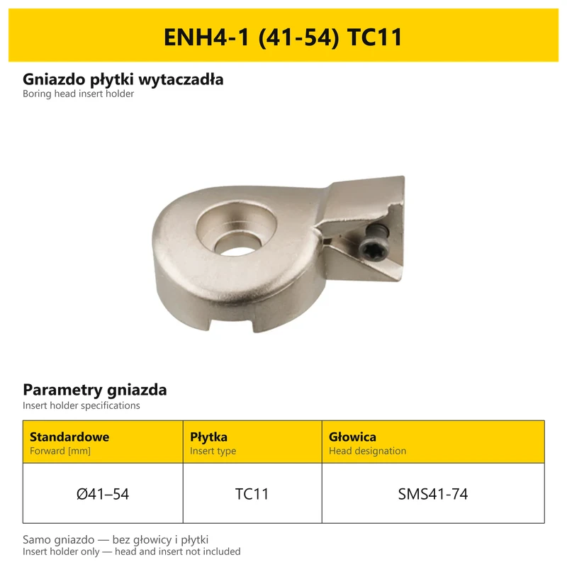
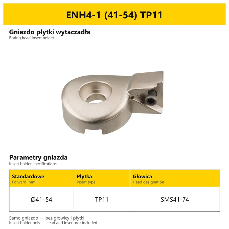
| ENH4-1 | SMS41-74 | 41–54 | — | TC11 / TP11 |
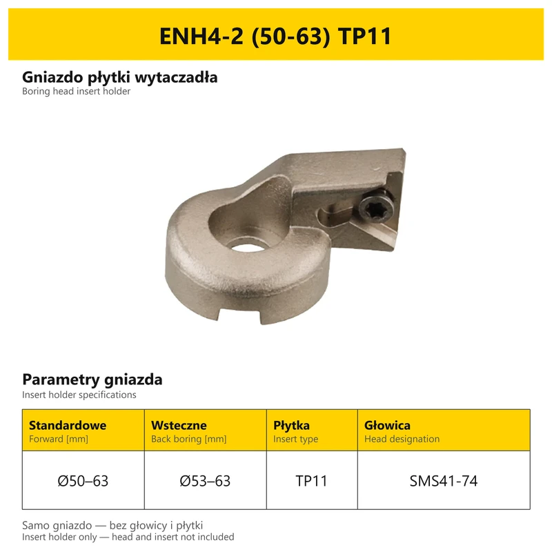
| ENH4-2 | SMS41-74 | 50–63 | 53–63 | TC11 / TP11 |
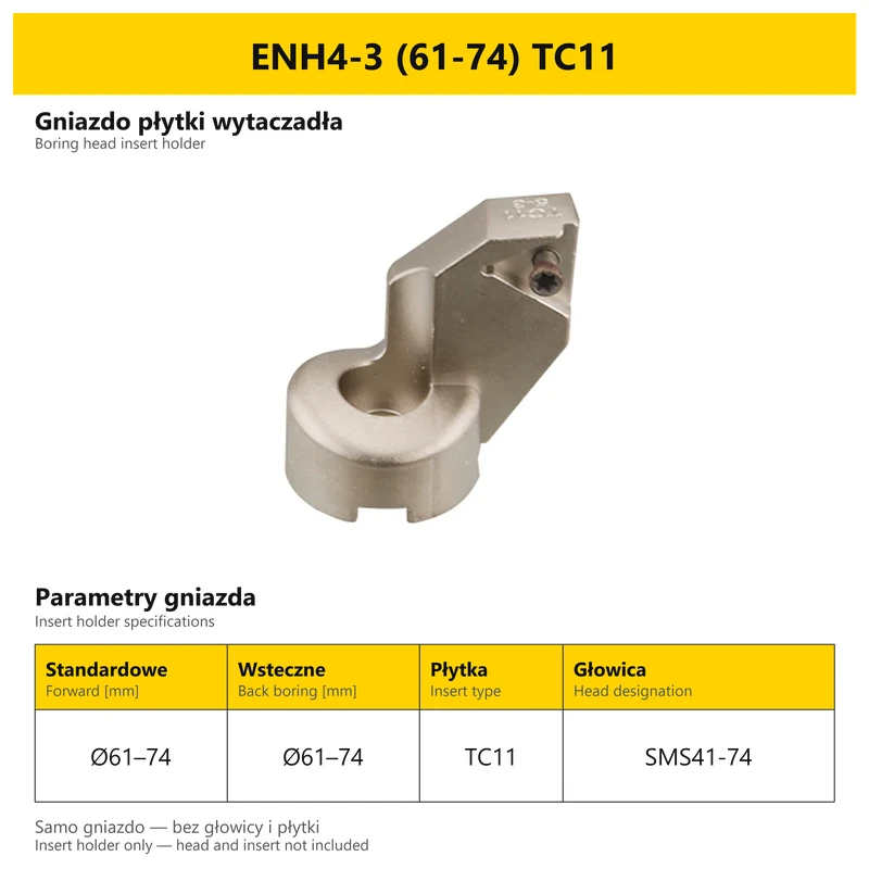
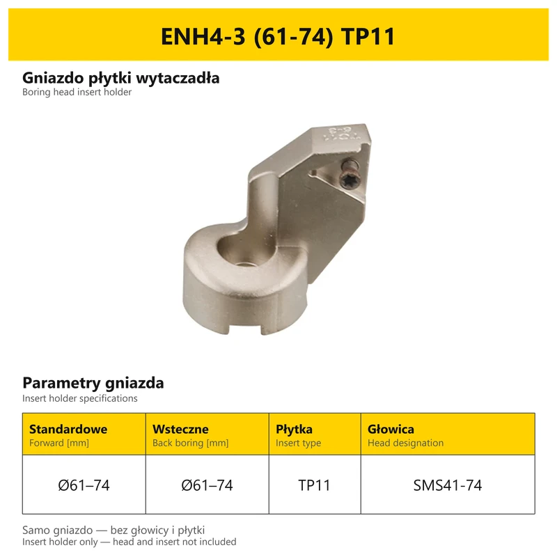
| ENH4-3 | SMS41-74 | 61–74 | 61–74 | TC11 / TP11 |
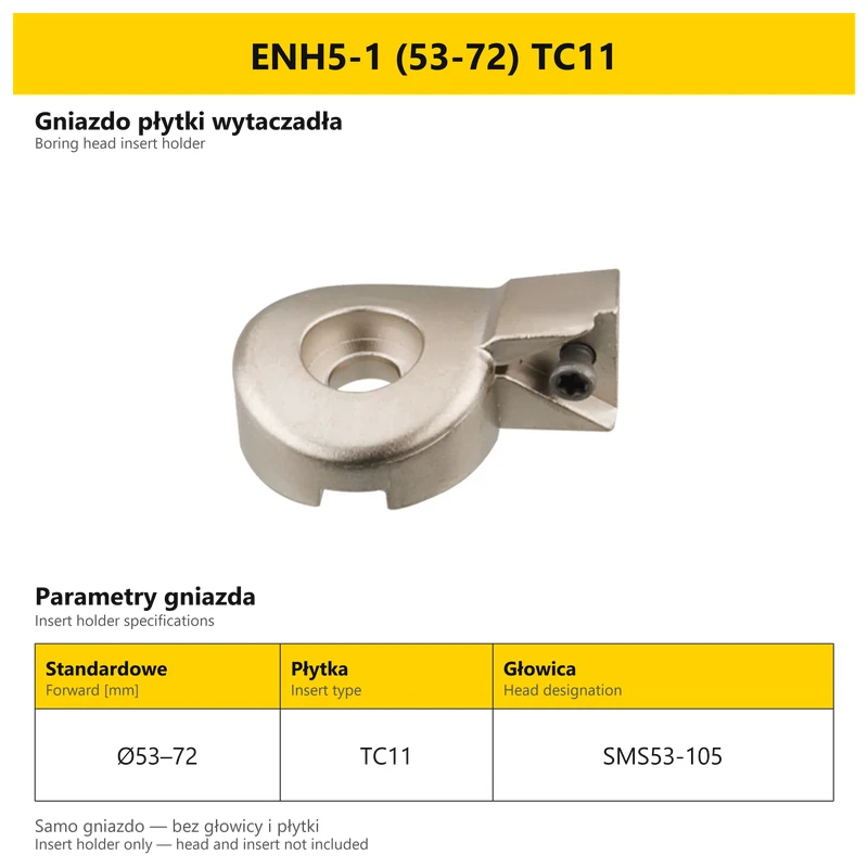
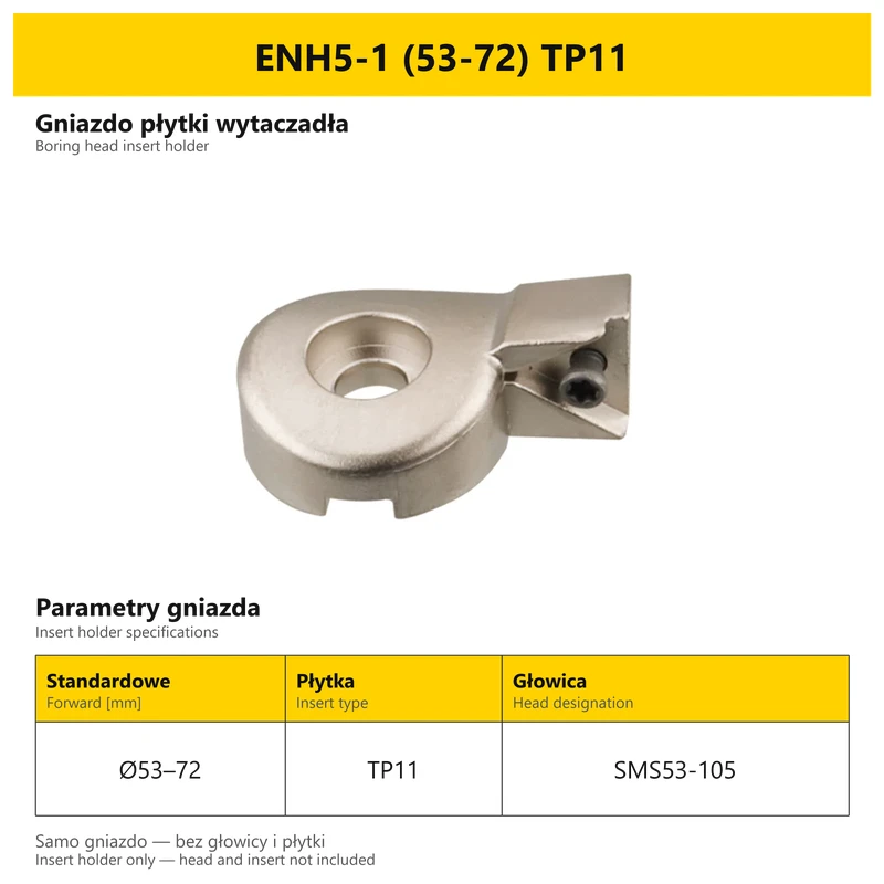
| ENH5-1 | SMS53-105 | 53–72 | — | TC11 / TP11 |
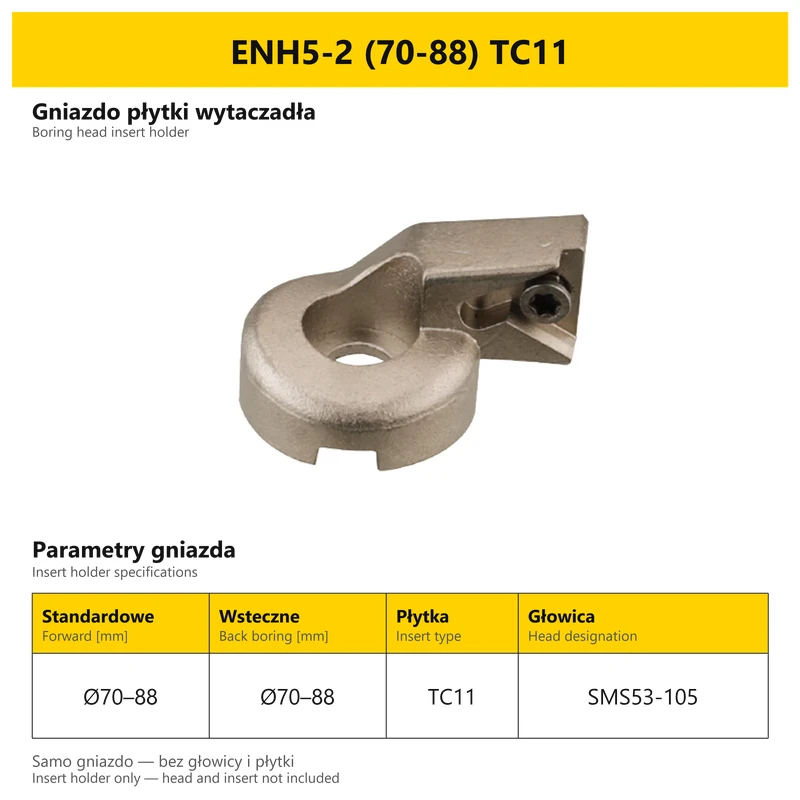
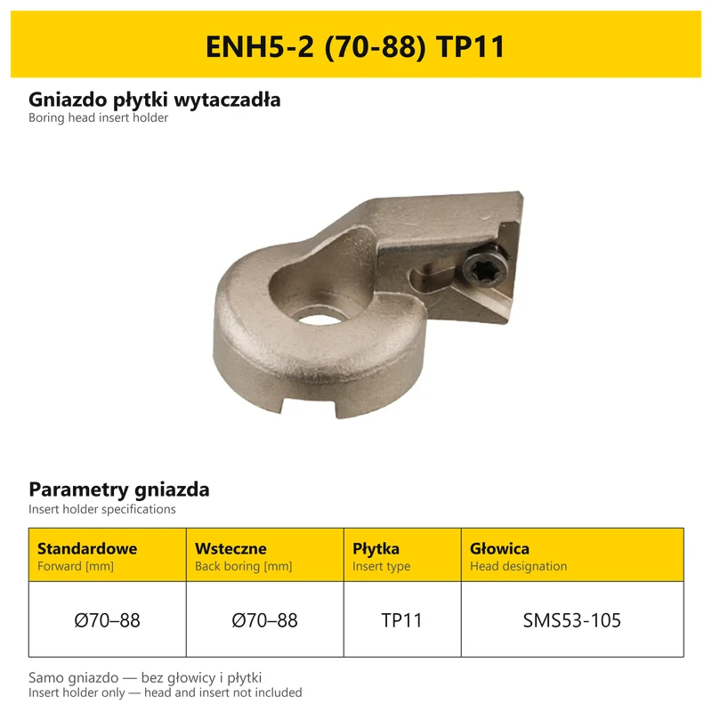
| ENH5-2 | SMS53-105 | 70–88 | 70–88 | TC11 / TP11 |
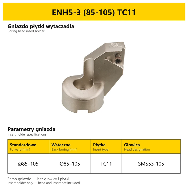
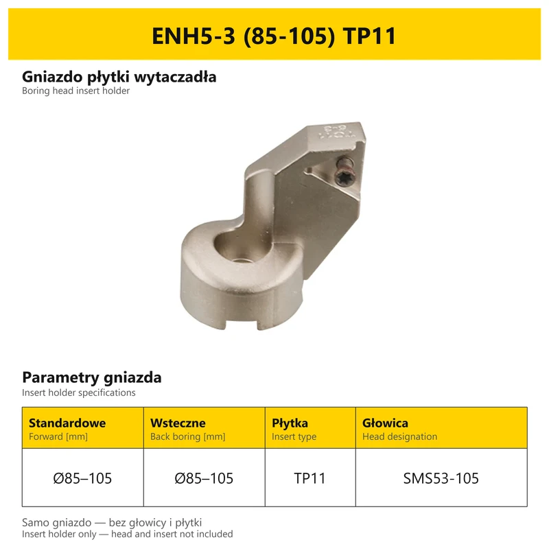
| ENH5-3 | SMS53-105 | 85–105 | 85–105 | TC11 / TP11 |
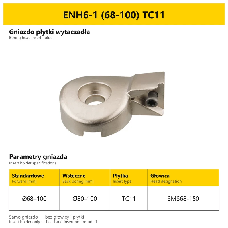
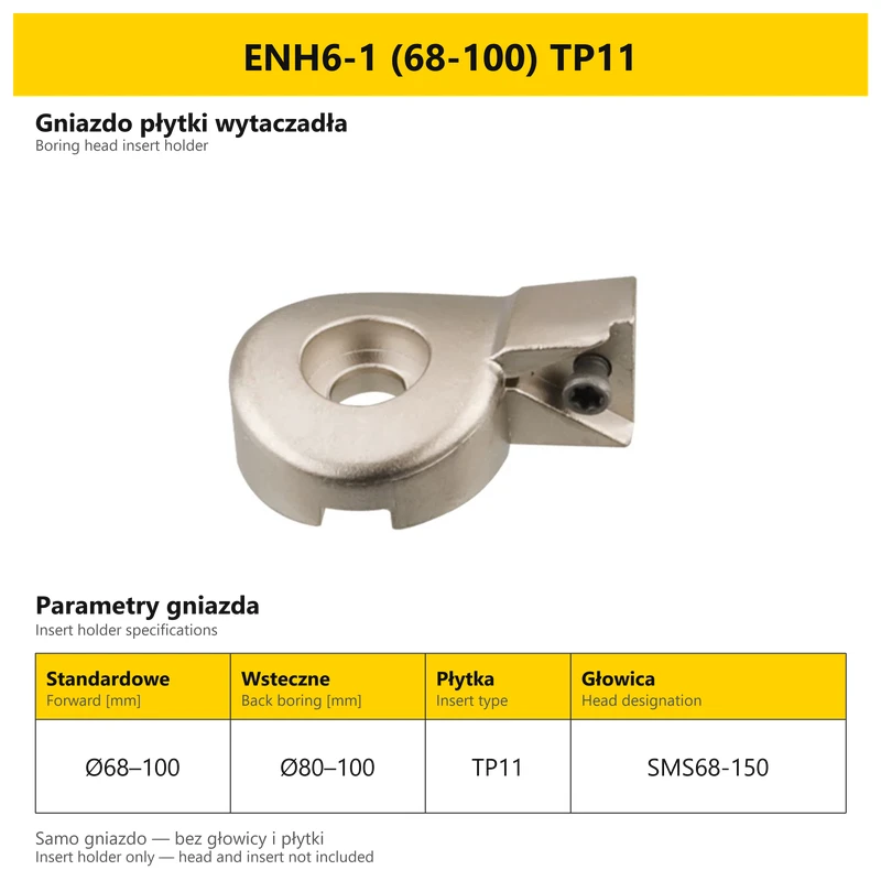
| ENH6-1 | SMS68-150 | 68–100 | 80–100 | TC11 / TP11 |
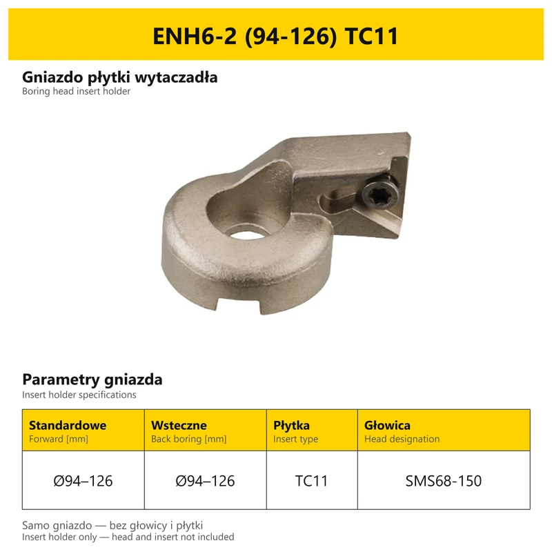
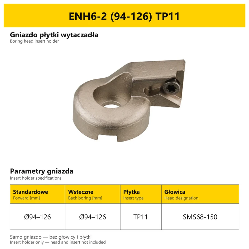
| ENH6-2 | SMS68-150 | 94–126 | 94–126 | TC11 / TP11 |
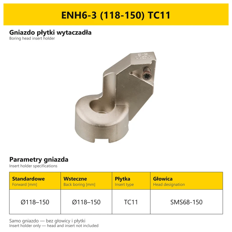
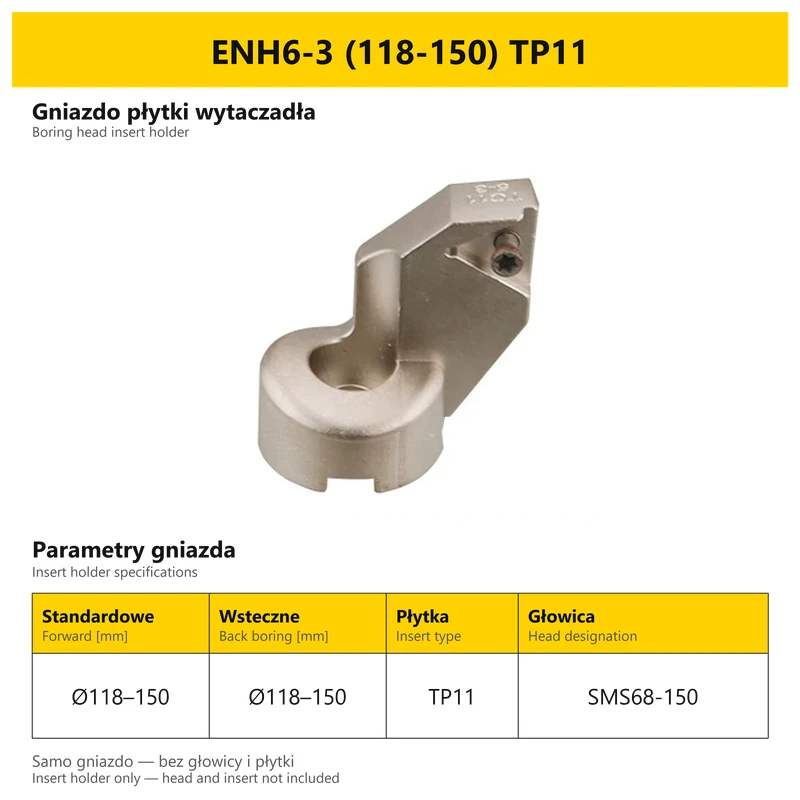
| ENH6-3 | SMS68-150 | 118–150 | 118–150 | TC11 / TP11 |
TC11 and TP11 denote separate holder versions, not two interchangeable insert choices for one holder. A dash is shown where no back-boring range is specified. Select an ENH option by its complete designation and insert family.
ENH5 and SMS53–95: the ENH5 holders in this table carry the SMS53–105 head designation and have their own ranges of 53–72, 70–88 and 85–105 mm. These are separate from the SMS53–95 head table. Similar 53–95 and 53–105 designations do not establish compatibility.
6. Scale and fine-adjustment sequence
One division changes the diameter setting by 0.01 mm, equivalent to 0.005 mm radially. This describes the mechanism setting, not a guaranteed finished-bore tolerance or roundness.
| Step | Action |
|---|---|
| 1 | Release the adjustment mechanism locking screw. |
| 2 | Turn the dial back by half a turn to take up clearance before the final setting. |
| 3 | Adjust the dial to the required diameter within the range of the head and insert holder. |
| 4 | Tighten the locking screw again after setting. |
7. Insert and mounting selection
| Head version | Insert system | Insert retaining screw |
|---|---|---|
| SMS20–36 / 25–47 / 32–60 | TP0802 (TP08) | M2×4 |
| SMS41–74 / 53–95 / 68–150 / 100–203 | TC1102 (TC11) | M2.5×6 |
| BST 200–310 / 300–410 / 400–510 | TC1102 (TC11) | M2.5×6 |
Cutting inserts are sold separately. The screw table applies to the listed head versions and insert systems; it does not extend that specification to optional TP11 holders. The LBK or BST head connection and the insert retaining screw are separate interfaces.
8. Questions before selection
Is the head range enough to choose a holder?
No. Check the holder number, its own forward and back ranges and its insert type.
Is an ENH holder a complete boring head?
No. An ENH option is a separate insert holder, without the head or cutting insert.
Does back boring have the same range as forward boring?
Not always. Use the two separate rows for the head, or the card for the particular holder.
What should be checked when selecting a bridge head?
The internal or external diameter range, overall height, BST interface and TC1102 insert system.
Related products
-
5A31-62406

 Milling Inserts 0.00
Carbide Turning Inserts TCMT/TBGT/TPGH/TCGT, WBGW, TBGW, TPGW, TCGW, TBMT, TPMT, TPMH, TCGH | VHM (10SZT.)
-
A6B5-108F4

 Boring Bars 0.00
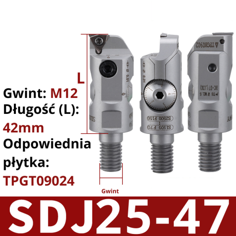
Precision Boring Head SDJ 10-12 | 12-14 | 14-17 | 16-21 | 20-28


Bestsellers
-
Bestseller
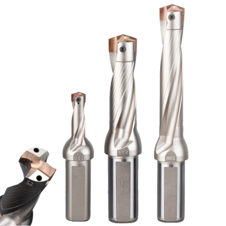
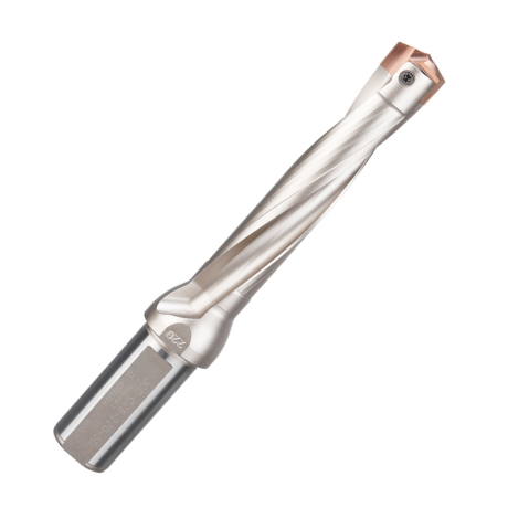
JCD modular drill with replaceable tip - internal cooling, for deep holes | GrotXD
JCD C20-100-3D Ø10~10.9 JCD C20-110-3D Ø11~11.9 JCD C20-120-3D Ø12~12.9 JCD C20-130-3D Ø13~13.9 JCD C20-140-3D Ø14~14.9 + 61 morePrice €69.52Price €56.52without VAT -
Price €17.09Price €13.90without VAT
-
Price €7.07Price €5.74without VAT
-
Price €7.52Price €6.12without VAT
-
Bestseller
 Other Accessories 0.00
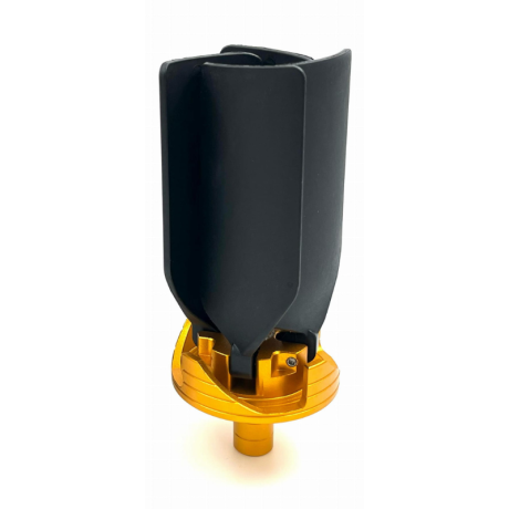
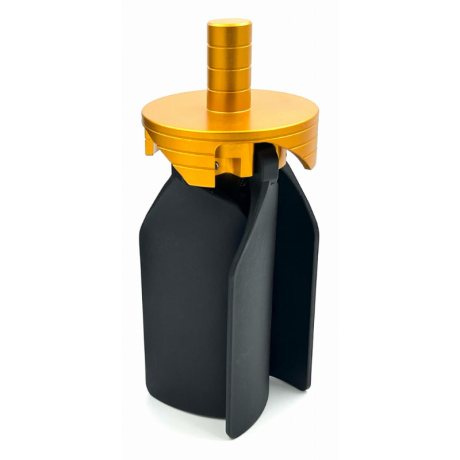
CNC Chip Fan / Chip Blower
Complete CNC chip fan Kit: blades, springs, pins and screwsPrice €53.56Price €43.55without VAT -
Bestseller
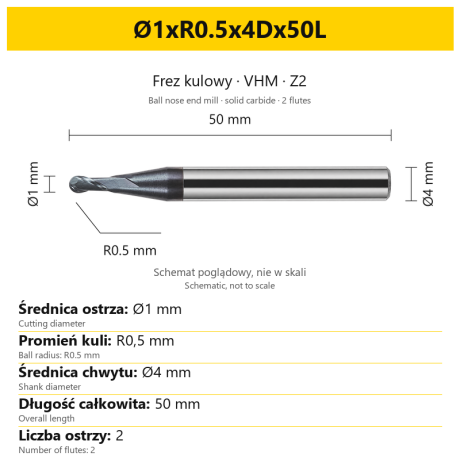 Ball Nose End Mills 0.00
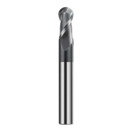
2-Flute Carbide Ball Nose End Mill - HYPERCUT
Ø1xR0.5x4Dx50L Ø1.5xR0.75x4Dx50L Ø2xR1x4Dx50L Ø2.5xR1.25x4Dx50L Ø3xR1.5x3Dx50L + 26 morePrice €10.09Price €8.21without VAT -
Bestseller
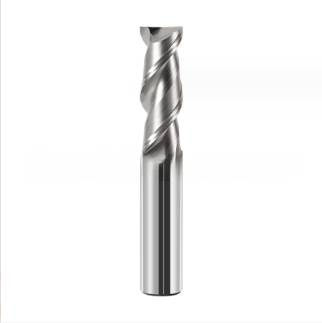
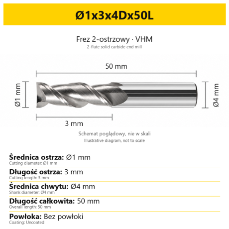 2-Flute End Mills 0.00
2-Flute Carbide End Mill for Aluminium
Ø1x3x4Dx50L Ø1.5x4x4Dx50L Ø2x6x4Dx50L Ø2.5x7.5x4Dx50L Ø3x9x3Dx50L + 31 morePrice €5.33Price €4.33without VAT -
Bestseller
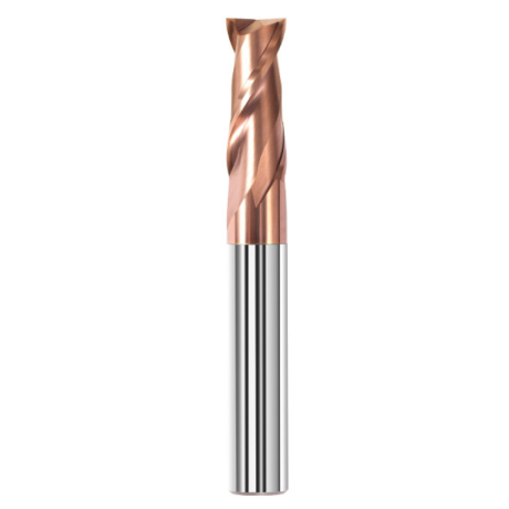
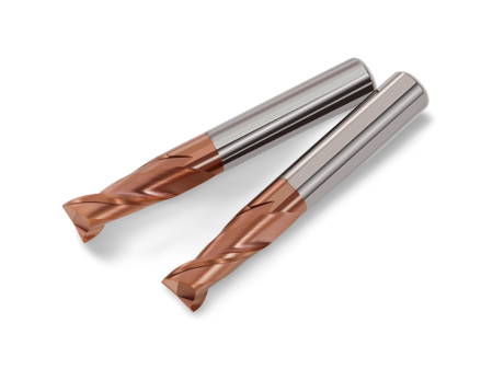 2-Flute End Mills 0.00
2-Flute Carbide End Mill for Steel 55 HRC - TiSiN - Solid Carbide
Ø6x24x6Dx75L Ø8x25x8Dx75L Ø4x20x4Dx100L Ø5x30x5Dx100L Ø6x30x6Dx100L + 31 morePrice €4.38Price €3.56without VAT -
Bestseller
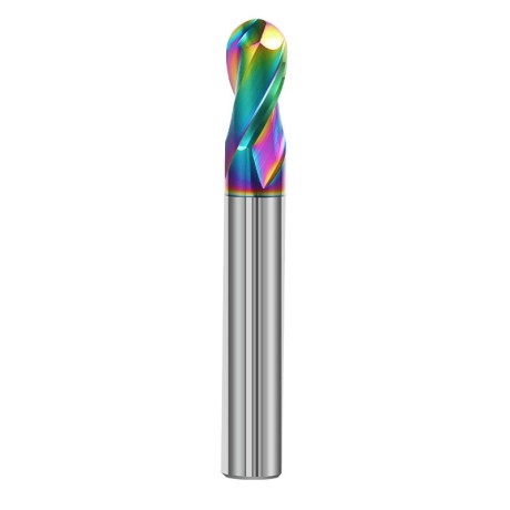
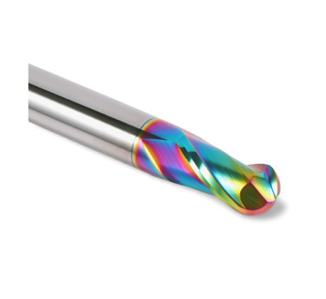 Ball Nose End Mills 0.00
2-Flute DLC Coated Carbide Ball Nose End Mill| DuraEdge Alu
Ø1.0xR0.5x4Dx50L Ø1.5xR0.75x4Dx50L Ø2.0xR1x4Dx50L Ø2.5xR1.25x4Dx50L Ø3.0xR1.5x3Dx50L + 34 morePrice €7.85Price €6.38without VAT -
Bestseller
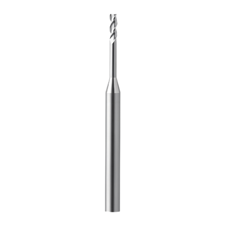
 2-Flute End Mills 0.00
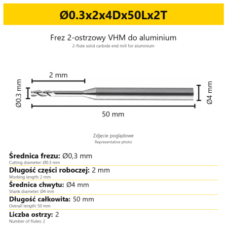
2-Flute End Mill for Aluminium | VHM | Miniature Ø0.3 - Ø0.9
Ø0.3x2x4Dx50Lx2T Ø0.3x3x4Dx50Lx2T Ø0.3x4x4Dx50Lx2T Ø0.4x2x4Dx50Lx2T Ø0.4x3x4Dx50Lx2T + 28 morePrice €7.95Price €6.47without VAT -
Bestseller
 Ball Nose End Mills 0.00
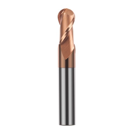
2-Flute TiSiN Coated Carbide Ball Nose End Mill
Ø1xR0.5x4Dx50L Ø1.5xR0.75x4Dx50L Ø2xR1x4Dx50L Ø2.5xR1.25x4Dx50L Ø3xR1.5x3Dx50L + 38 morePrice €7.24Price €5.89without VAT -
Bestseller
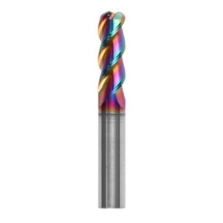
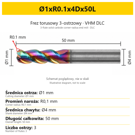
3-Flute Carbide Corner Radius End Mill for Aluminium| AL DLC
Ø1xR0.1x4Dx50L Ø1xR0.2x4Dx50L Ø1xR0.3x4Dx50L Ø1.5xR0.1x4Dx50L Ø1.5xR0.2x4Dx50L + 137 morePrice €5.89Price €4.79without VAT -
Bestseller
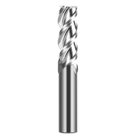
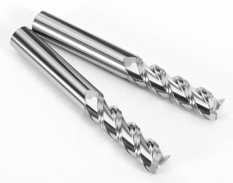 3-Flute End Mills 0.00
3-Flute Carbide End Mill VHM Z-3 for Aluminium| TriMill AL
Ø1x3xD4x50L Ø1.5x5x4Dx50L Ø2x6x4Dx50L Ø2.5x8x4Dx50L Ø3x9x3Dx50L + 41 morePrice €5.08Price €4.13without VAT -
Bestseller
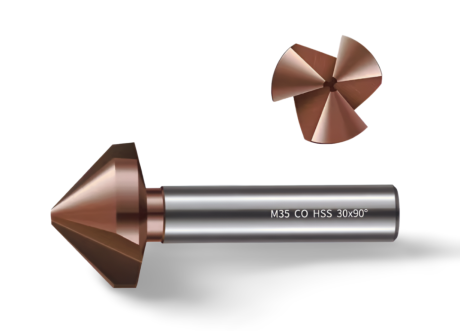
 Countersinks 0.00
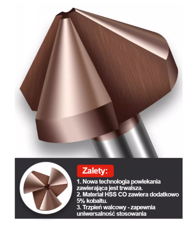
3-Flute Countersink Fi4.5-fi60, 90° - HSS-CO - 5% Kobaltu | Straight Shank
Ø4.5 x 4 x 90° x 40L Ø5 x 5 x 90° x 45L Ø6.3 x 5 x 90° x 45L Ø8.3 x 6 x 90° x 50L Ø10.4 x 6 x 90° x 50L + 12 morePrice €4.79Price €3.89without VAT -
Bestseller
 3-Flute End Mills 0.00
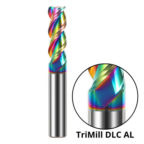
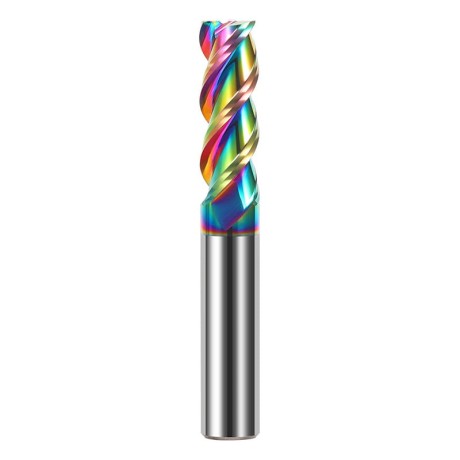
3-Flute DLC Coated Carbide End Mill | TriMill DLC AL
Ø1x3x4Dx50L Ø1.5x5x4Dx50L Ø2x6x4Dx50L Ø2.5x8x4Dx50L Ø3x8x3Dx50L + 38 morePrice €5.05Price €4.10without VAT -
Bestseller

 3-Flute End Mills 0.00
3-Flute HRC65 DLC Coated Carbide End Mill, U-Shaped Flute, for Aluminium | DuraEdge3 Alu
Ø1x3x4Dx50L Ø1.5x5x4Dx50L Ø2x6x4Dx50L Ø2.5x8x4Dx50L Ø3x9x3Dx50L + 40 morePrice €6.73Price €5.47without VAT