€705.27 incl. VAT
Lowest price in the 30 days before the reduction: €796.27
€573.39 excl. VAT
Choose variant
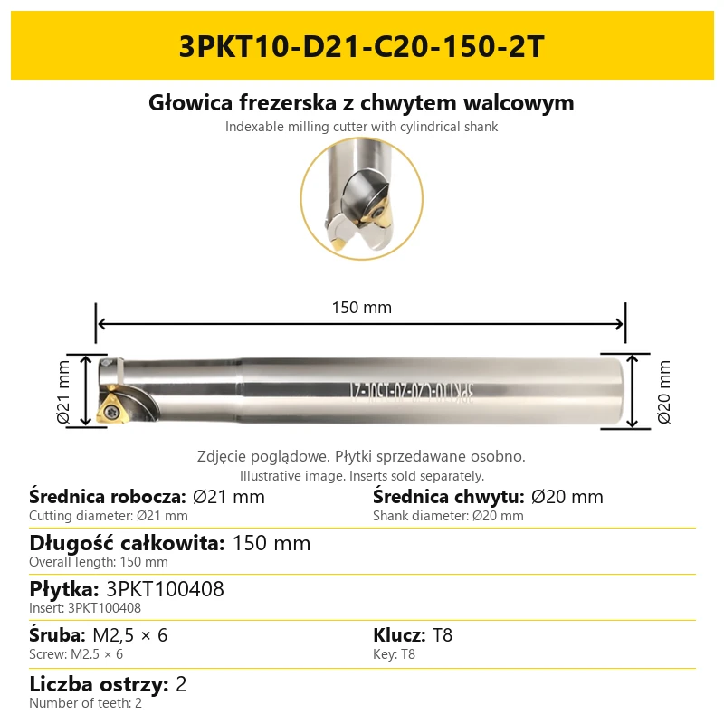
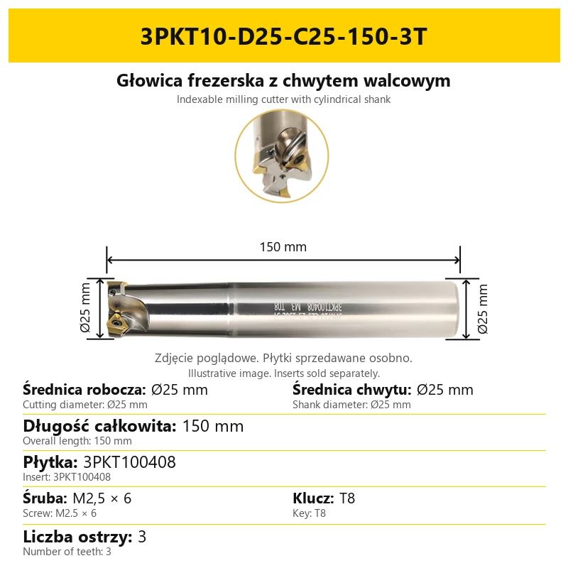
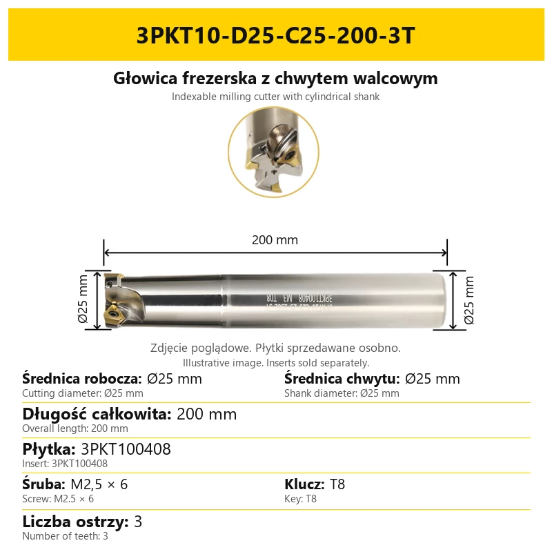
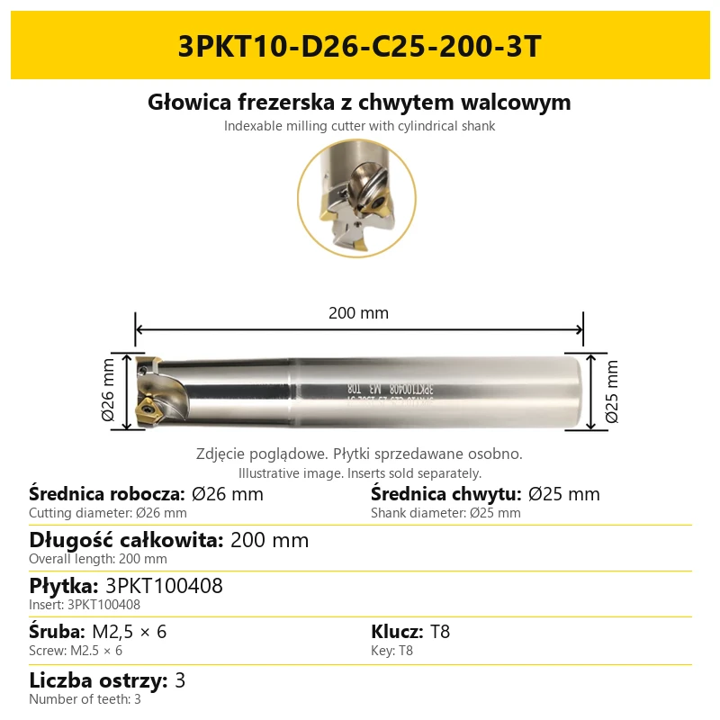
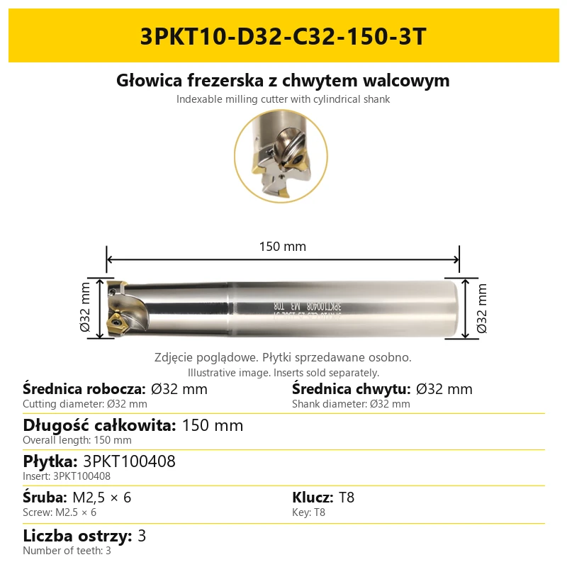
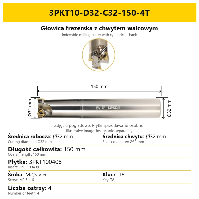
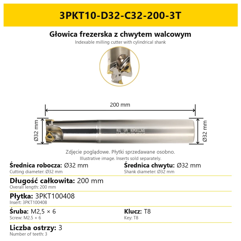
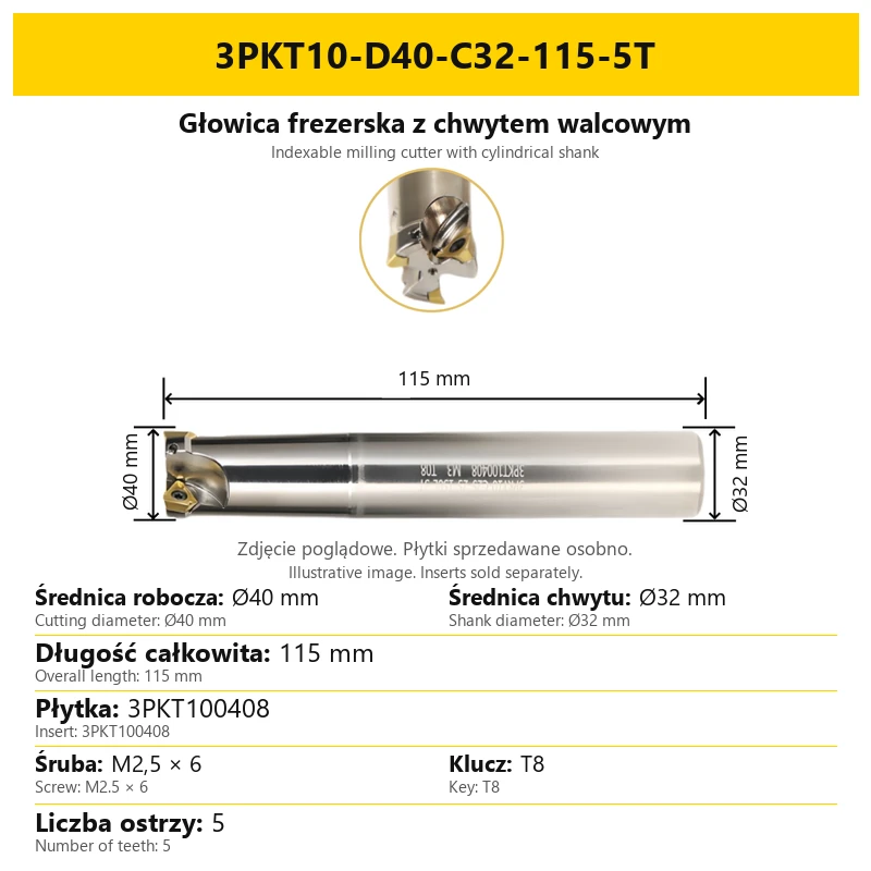
Shipping costs are not included in the price.
Shipping costs are not included in the price.

Weekly deals · −11%
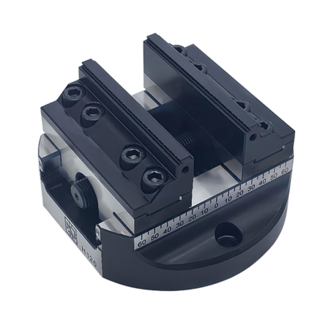
Self-centering machine vise. Hard jaws included.
€573.39 excl. VAT
Regular price: €796.27
Lowest price in the 30 days before the reduction: €796.27
Time left
Offer ends 06.11.2026 23:59. Offer applies to the vise + hard jaws bundle only.
Lowest price in the 30 days before the reduction: €796.27
€573.39 excl. VAT
Choose variant
Weekly deals · −5%
MFPN66-50-22-4T
€47.44 excl. VAT
Regular price: €61.43
Lowest price in the 30 days before the reduction: €61.43
Time left
Offer ends 06.11.2026 23:59.

Weekly deals · −5%
MFPN66-50-22-4T
€57.11 excl. VAT
Regular price: €73.94
Lowest price in the 30 days before the reduction: €73.94
Time left
Offer ends 06.11.2026 23:59.

The administrator of personal data is Kortools. We process it to respond to your inquiry. More information regarding the processing of personal data can be found in privacy policy.
Select a product variant:
Individual variants may differ in price
Product code: B285-4517A
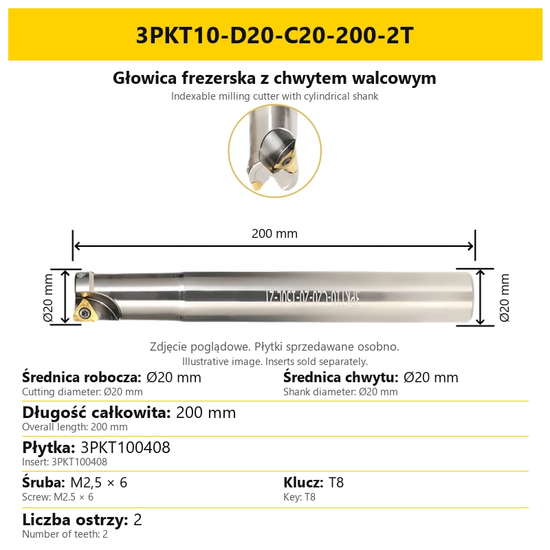
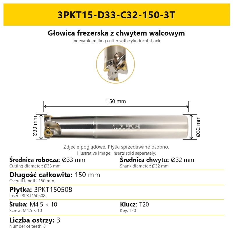
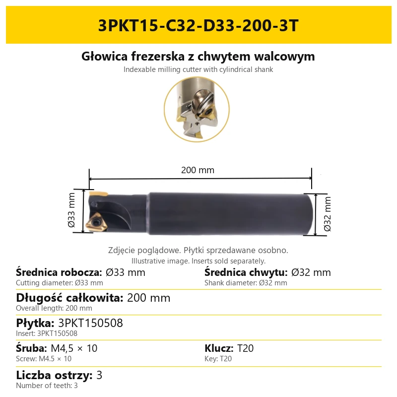
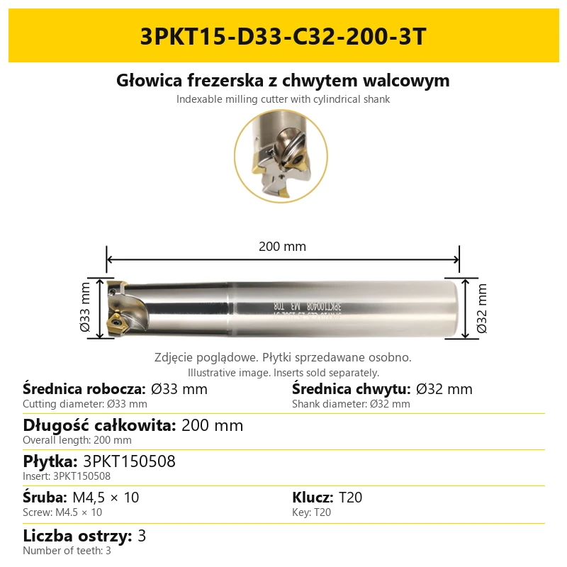
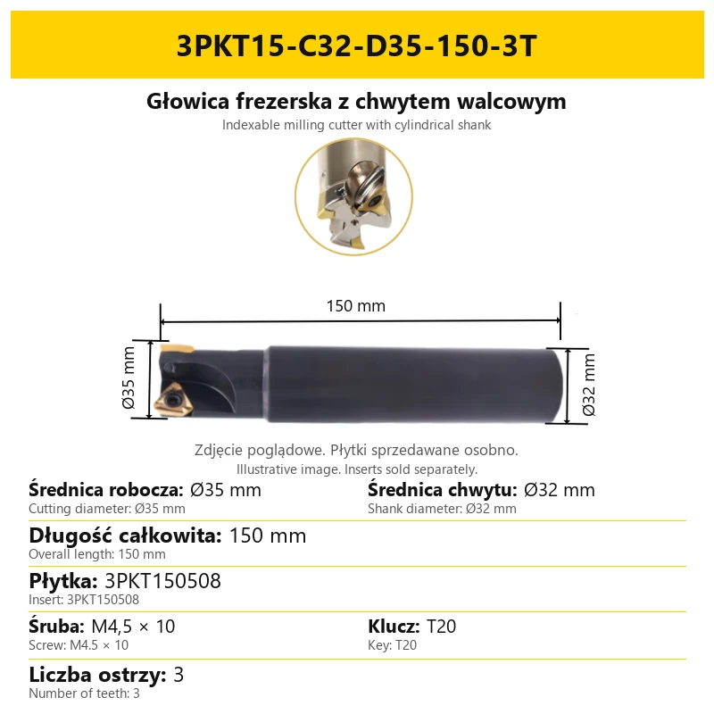
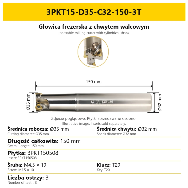
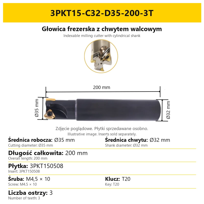
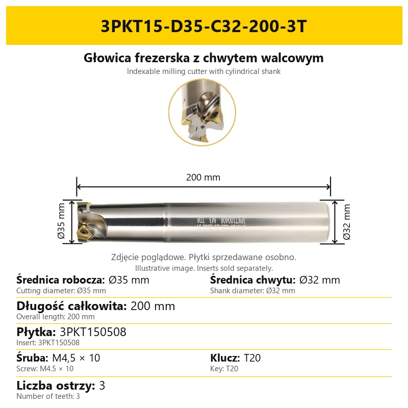
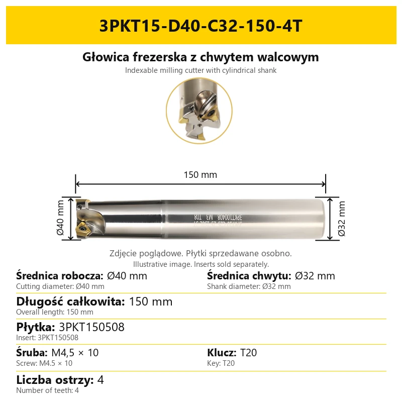
The 3PKT cylindrical-shank milling cutter uses replaceable cutting inserts. The cutting head and shank form one tool; select the insert for the pocket family, 3PKT10 or 3PKT15.
The body is made of 42CrMo alloy steel. Induction hardening provides hardness and resistance to deformation. Replaceable cutting inserts are secured by screws in the pockets.
| Parameter | Information |
|---|---|
| Tool type | Indexable milling cutter |
| Mounting | Cylindrical shank |
| Body material | 42CrMo alloy steel |
| Heat treatment | Induction hardening |
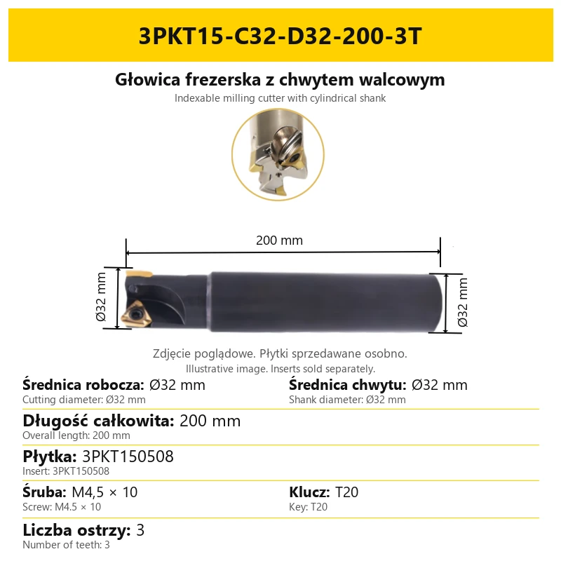
| Insert families | 3PKT100408 / 3PKT150508, depending on variant |
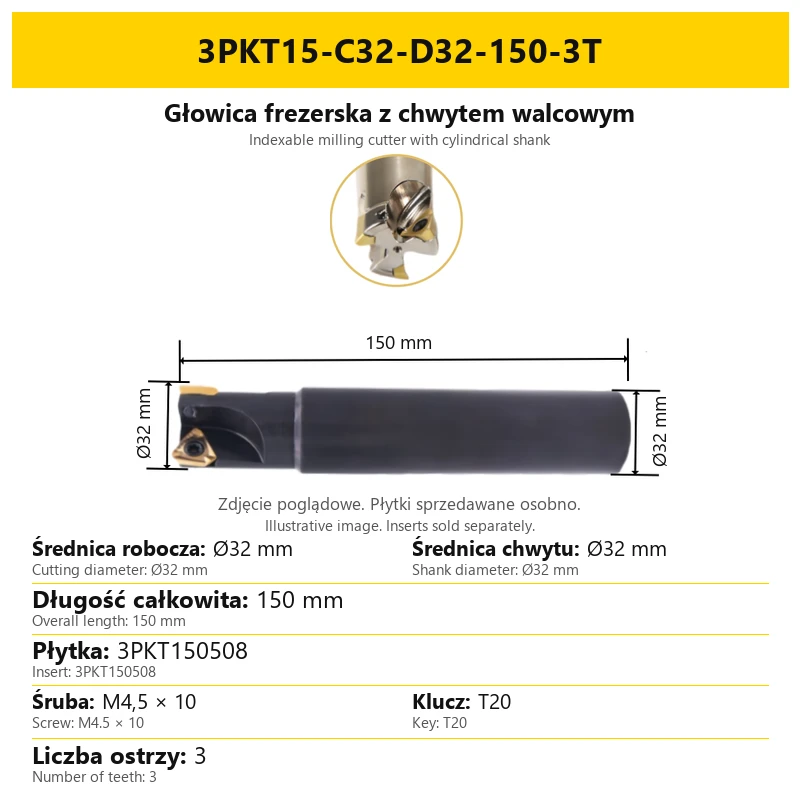
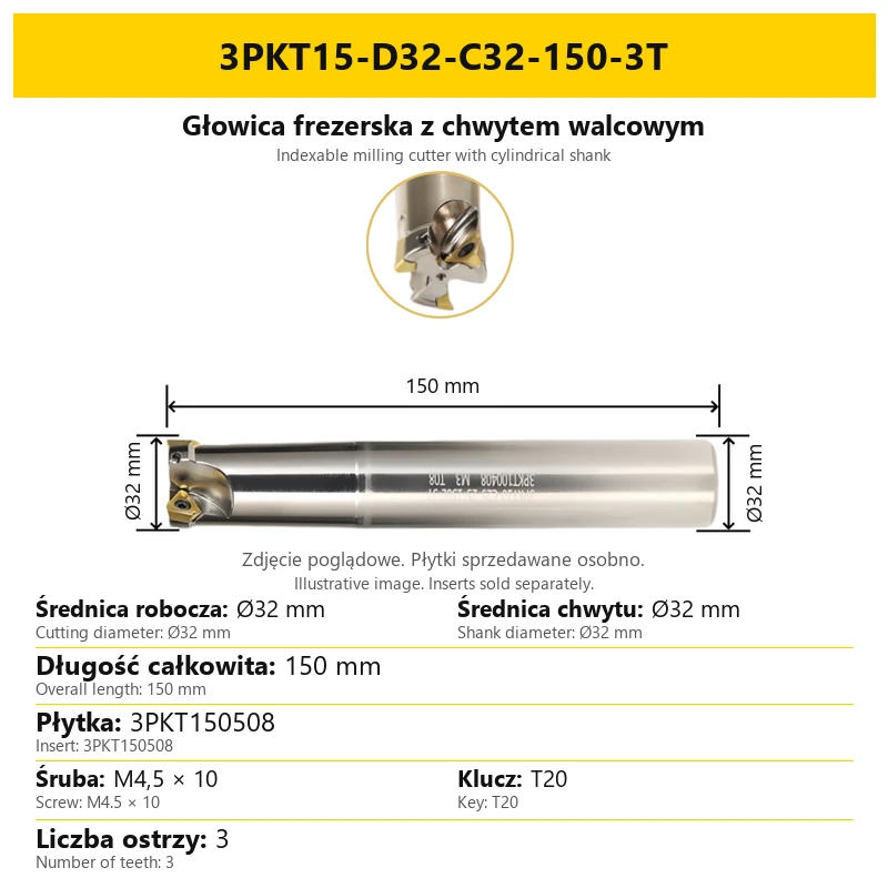
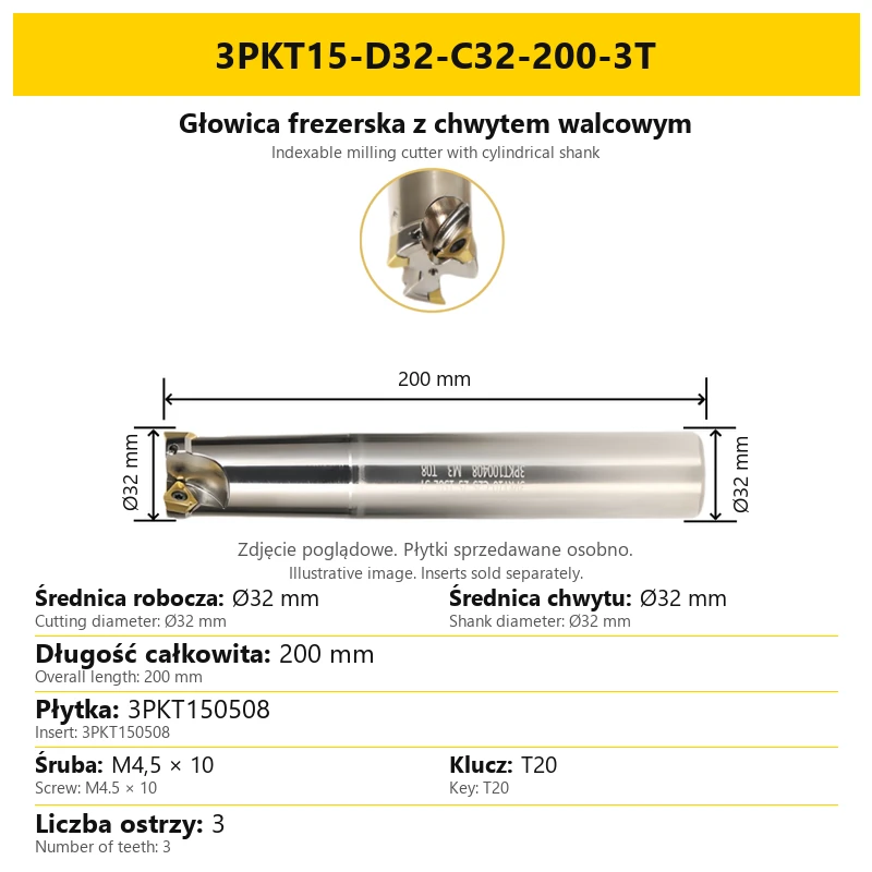
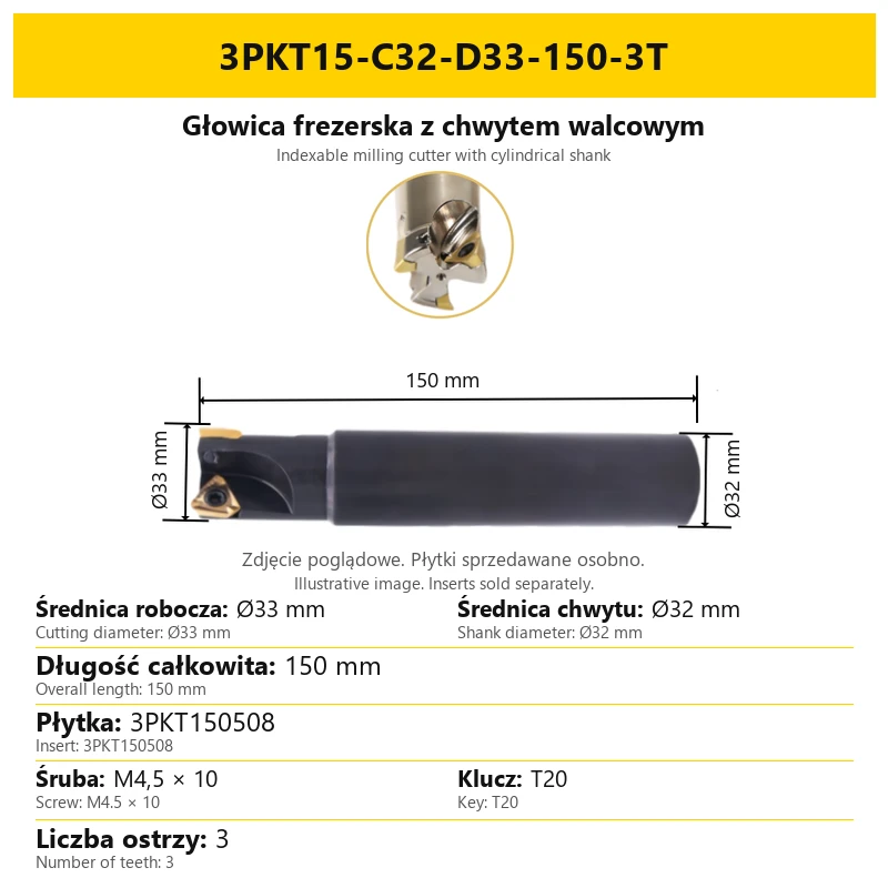
Cutting inserts are sold separately. Images show inserts fitted to illustrate their position in the pockets. This does not mean inserts are supplied with the body.
This tool family is intended for roughing and finishing. Applications include face, shoulder and side milling. Compare the selected cutter geometry, mounting dimensions and insert type before making a selection.
| Selection factor | Purpose |
|---|---|
| Body and mounting | Define the cutting diameter and the connection to the toolholder. |
| Replaceable insert | Its type must match the pocket of the selected body. |
| Insert grade and geometry | Selected for the workpiece material and type of operation. |
| Number of teeth | Specified in the designation and on the particular variant card. |
The body code does not specify the insert grade. When purchasing inserts, consider the workpiece material and required operation; the cutter card identifies the matching insert type.
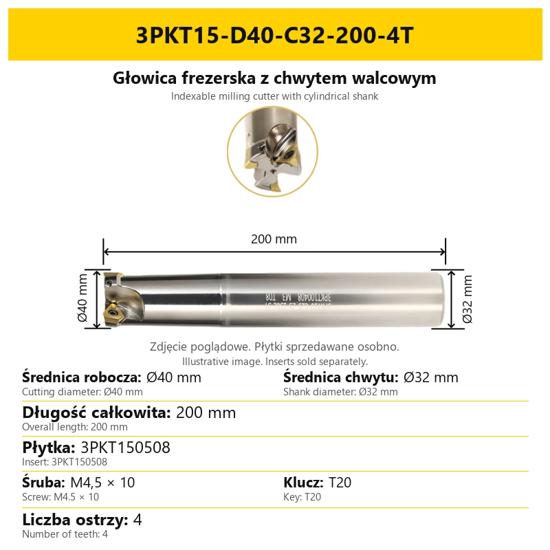
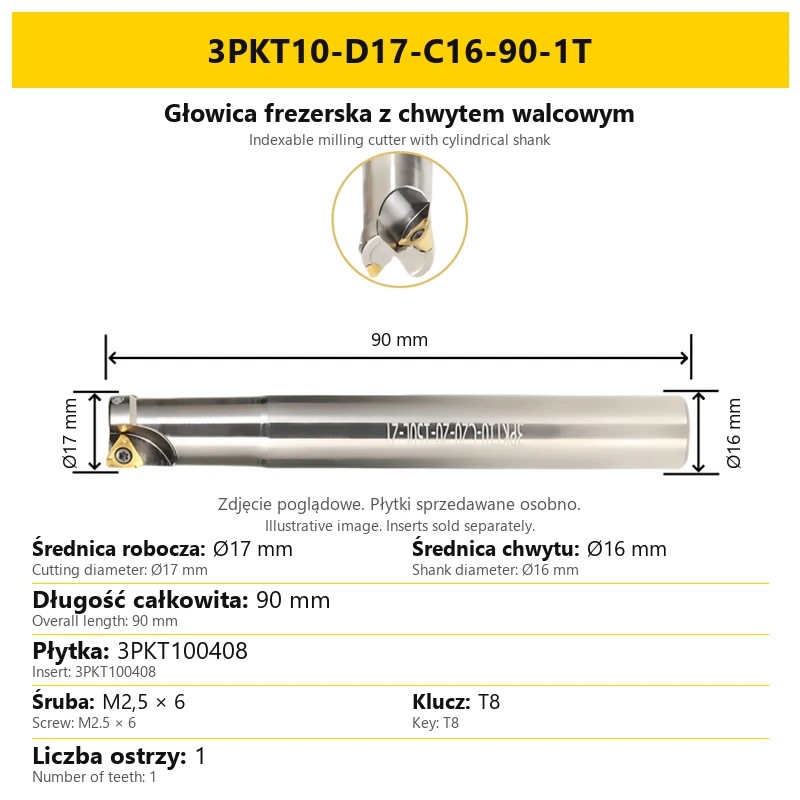
Cutting diameter and shank diameter are separate parameters and may be equal or different. Overall length includes the complete cutting head and shank.
| Parameter | Range / meaning |
|---|---|
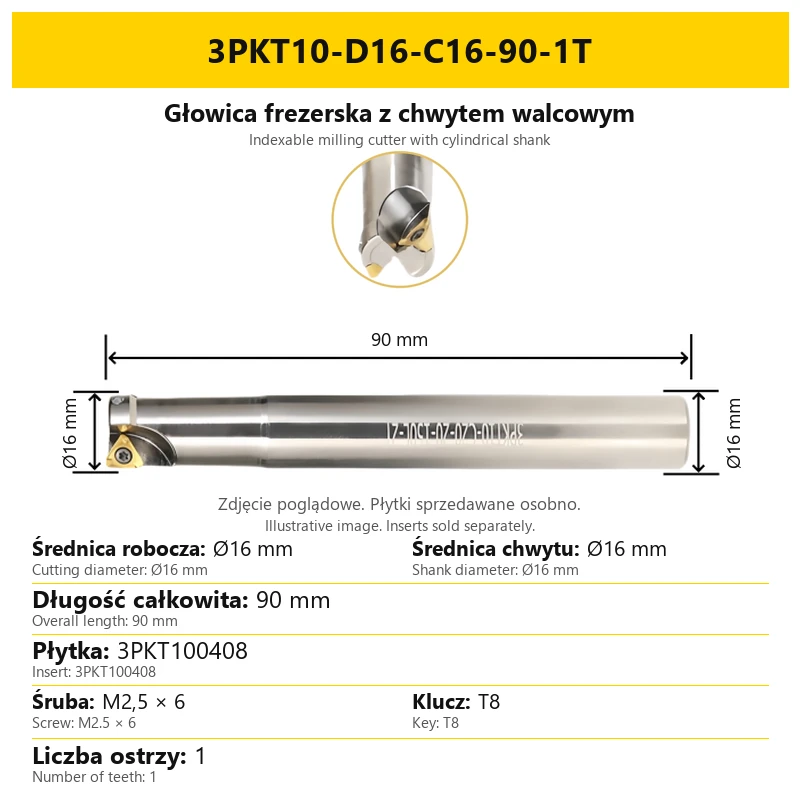
| Cutting diameter D | Ø16–Ø40 mm |
| Shank diameter C | Ø16, Ø20, Ø25 or Ø32 mm |
| Overall length L | 90, 115, 150 or 200 mm |
| Number of teeth T | From 1 to 5, depending on the selected body |
Dimensions are offered in specific combinations, not every possible combination. The selected variant card shows the correct set of D, C, L and T.
The 3PKT15 family includes distinct body configurations with different appearances. Use the complete designation when selecting the tool; cutting diameter alone does not identify its configuration.
Images are illustrative. Select the tool using the dimensions and designation of the chosen variant rather than proportions in the photograph. The variant card states the cutting diameter, length and number of teeth.
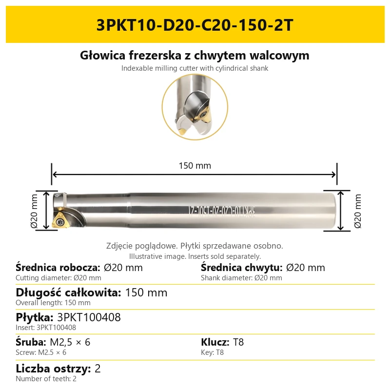
Example: 3PKT10-D20-C20-150-2T. The designation includes the insert family and basic tool dimensions.
| Code element | Meaning in the example |
|---|---|
| 3PKT10 | Body family for a 3PKT100408 insert |
| D20 | Ø20 mm cutting diameter |
| C20 | Ø20 mm shank diameter |
| 150 | 150 mm overall length |
| 2T | Two teeth |
Some designations reverse the order of the C and D elements. D still refers to cutting diameter and C to shank diameter. Do not interchange these values when selecting the toolholder.
| Family | Insert | Screw | Key |
|---|---|---|---|
| 3PKT10 | 3PKT100408 | M2.5 × 6 | T8 |
| 3PKT15 | 3PKT150508 | M4.5 × 10 | T20 |
Select the insert by its pocket designation and the screw and key using the table for the relevant family. The number of teeth specifies how many pockets are populated in the selected cutter.
The screw secures the insert in the body. Its size is not the tool shank diameter. T8 or T20 identifies the key used for the insert screw.
Cutting inserts are sold separately. Images show inserts fitted to illustrate their position in the pockets. This does not mean inserts are supplied with the body.
| Item to check | What to compare |
|---|---|
| Tool shank | Diameter C against the toolholder connection. |
| Cutting head | Diameter D against the required cutting diameter. |
| Length | Overall length L specified for the selected variant. |
| Insert pockets | Insert type, correct screw and proper seating. |
Accurate insert seating and clamping in the pocket are part of the tool design. During servicing, check insert contact and the condition of the screw and pocket. Do not select fastening parts solely from the similar appearance of another cutter body.
The condition of replaceable inserts affects part dimensions and surface quality. The following points distinguish common symptoms; process settings must be related to the workpiece material, insert and clamping rigidity.
| Symptom | What to check |
|---|---|
| Gradual surface deterioration or dimensional change | Insert flank wear and cutting speed. For excessive wear, review the cutting parameters and insert grade. |
| Edge chipping | Insert selection, machining parameters, workpiece rigidity and correct insert clamping. |
| Sudden insert or tool failure | Insert seating, vibration, setup rigidity and loading from feed and cutting conditions. |
| Built-up edge and uneven surface | Cutting speed, feed and insert sharpness. Adjust parameters and cutting-edge geometry for the workpiece material. |
Do not use one set of parameters for all workpiece materials and insert grades. T denotes the number of teeth, not a recommended spindle speed or feed.
Are inserts included?
No. Purchase the insert type shown on the selected variant card separately.
Do D and C mean the same dimension?
No. D is cutting diameter and C is shank diameter. Their values may differ.
What does the number before T mean?
The number of teeth on the body. It is not the number of tools in a pack.
Does every 3PKT cutter use the same insert?
No. This listing includes families for 3PKT100408 and 3PKT150508 inserts. Match the insert to the specific body designation.
Can length be determined from the photograph?
No. The image is illustrative; the correct length is stated numerically on the card and in the variant designation.


Cookies and related technologies allow the website to function properly and help us adjust the offer to your needs. You can choose to accept our use of all these files and go to the store, or adapt the use of files to your preferences by selecting "Customize Consents".
Here you can define your preferences regarding the use of cookies.
These files are necessary for our website to function so they can't be switched off.
These files allow you to use other functions of the website (other than those necessary for its functioning). Enabling these files will give you access to the full functionality of the website.
These files allow us to analyze our online store, which may contribute to its better functioning and adaptation to the needs of our Users.
With these files, we can conduct marketing activities.