

Indexable Slitting Cutter VHM | SlotCut Basic JP
Shipping costs are not included in the price.
Shipping costs are not included in the price.

Weekly deals
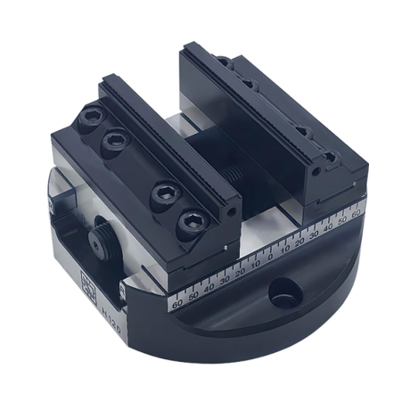
5-axis vise with hard jaws
Self-centering machine vise. Hard jaws included.
excl. VAT
Regular price:
Lowest price in the 30 days before the reduction:
Time left
Offer ends 06.11.2026 23:59. Offer applies to the vise + hard jaws bundle only.
Ask about the product

The administrator of personal data is Kortools. We process it to respond to your inquiry. More information regarding the processing of personal data can be found in privacy policy.
Select a product variant:
Individual variants may differ in price
Product code: 830A-34179
Product description
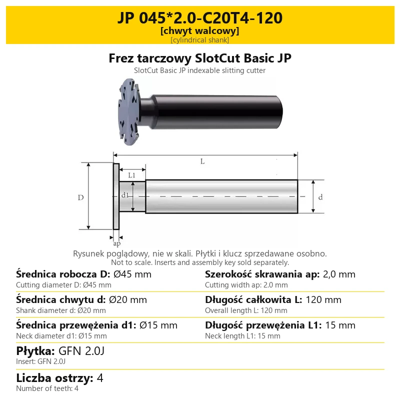
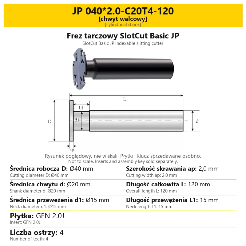
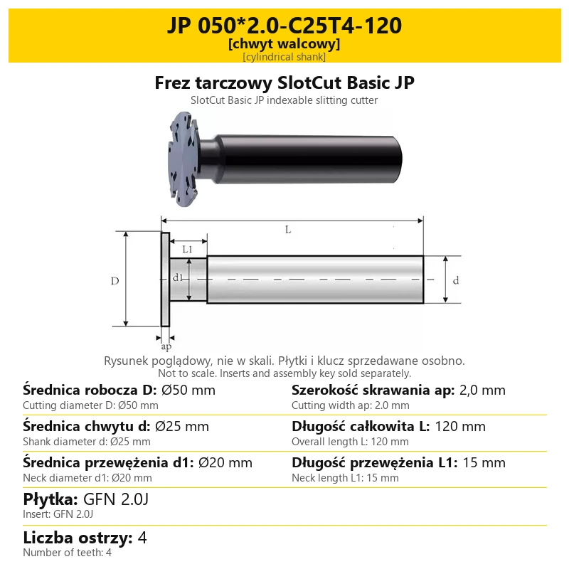
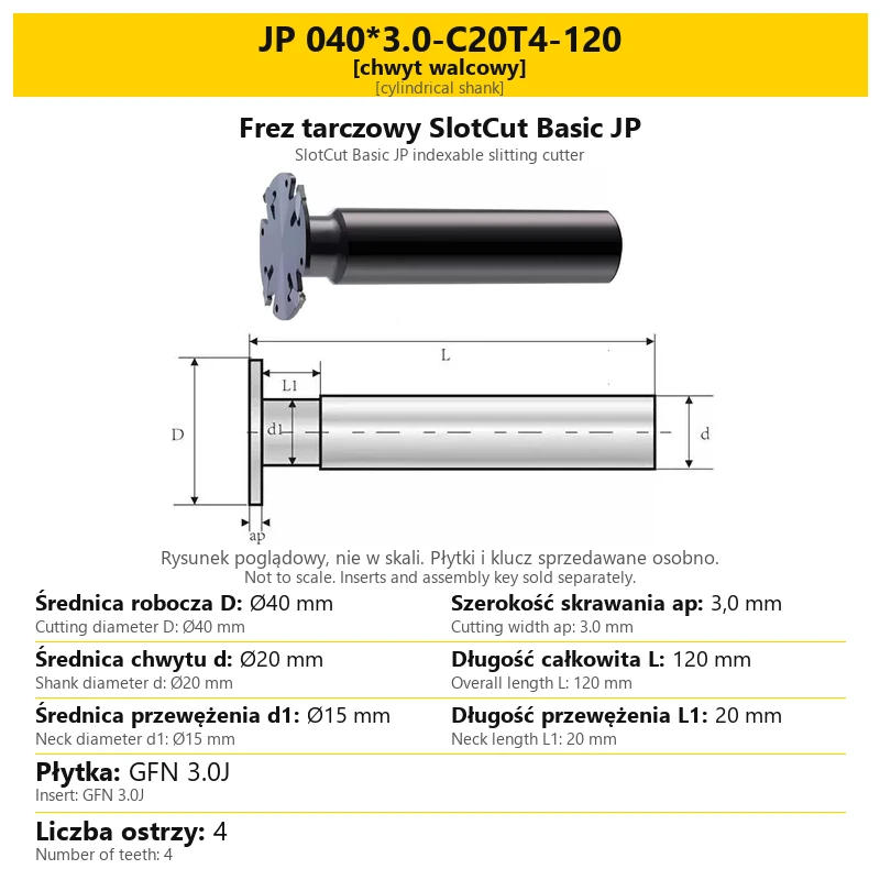
1. SlotCut Basic JP indexable slitting cutter
SlotCut Basic JP is an indexable slitting cutter for cutting-off operations. It uses replaceable solid carbide (VHM) inserts, mechanically seated in the body pockets. Inserts are installed using the appropriate assembly key.
The selected variant defines the cutting diameter, cutting width, number of teeth and mounting arrangement. The range includes cylindrical-shank cutters, cutter-and-FMB-arbor assemblies, and separately selected arbors and keys. Cutting inserts and the assembly key are sold separately from the cutter.
| Parameter | Information |
|---|---|
| Tool type | Indexable slitting cutter for cutting-off |
| Series | SlotCut Basic JP |
| Cutting elements | Replaceable solid carbide (VHM) inserts |
| Cutter body alloy | 42CrMo alloy steel |
| Insert mounting | Mechanical seating in body pockets |
2. Configurations and mounting
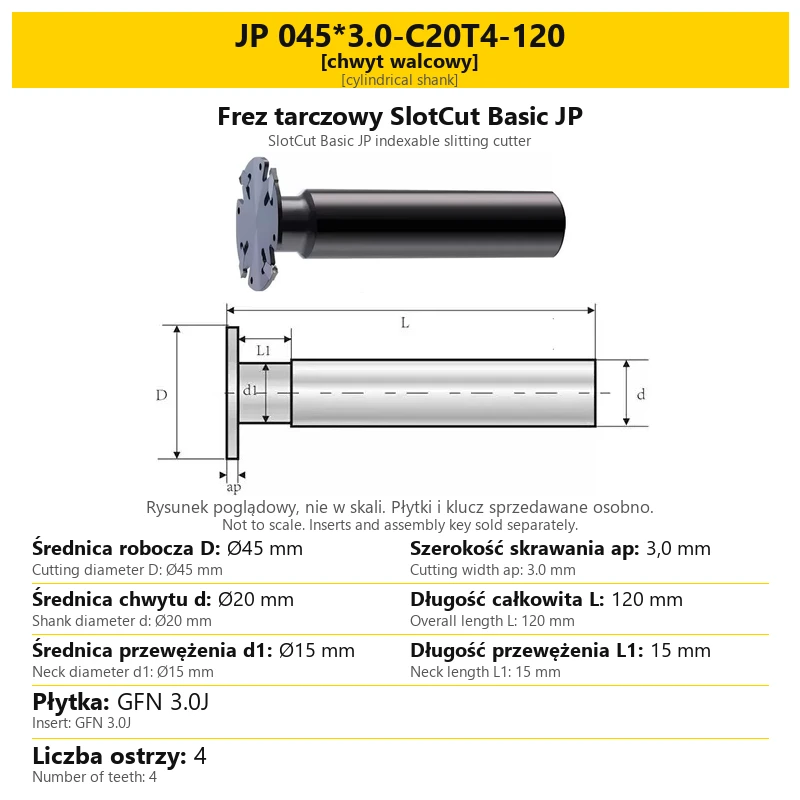
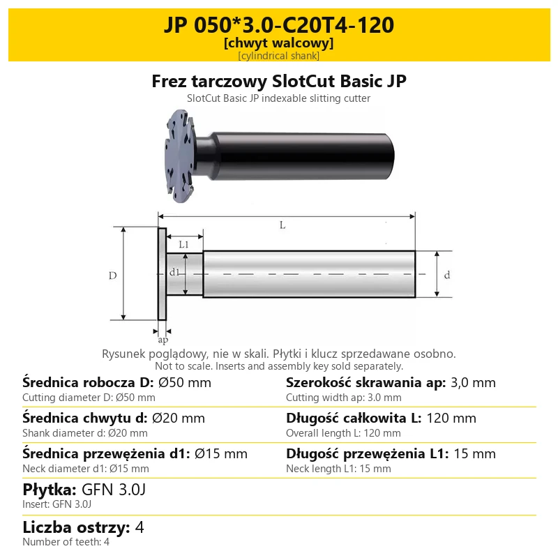
Choose a configuration for the holder fitted to the machine. Cutter diameter is different from shank diameter and mounting bore diameter. Each is labelled separately on the variant card.
| Configuration | Meaning | Check |
|---|---|---|
| Cylindrical shank | The cutting head is connected to a shank of the specified diameter. | Shank diameter d, length L and neck dimensions. |
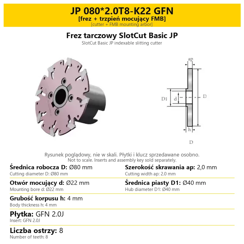
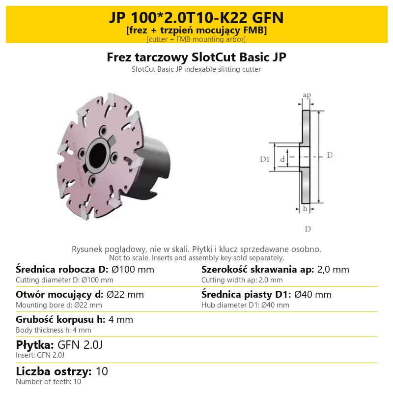
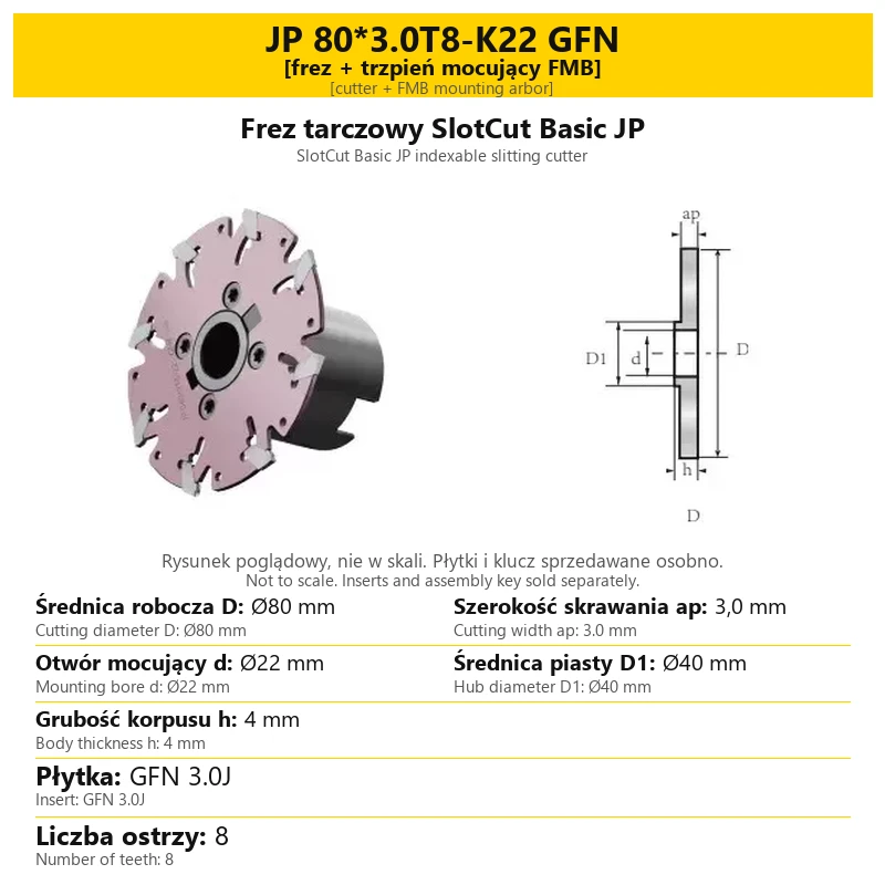
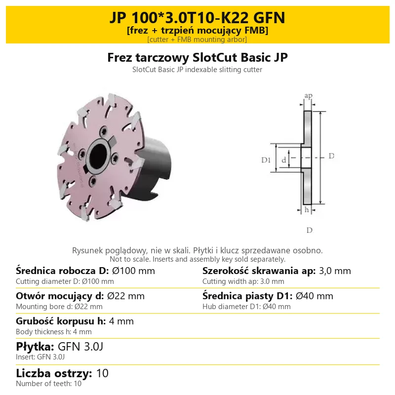
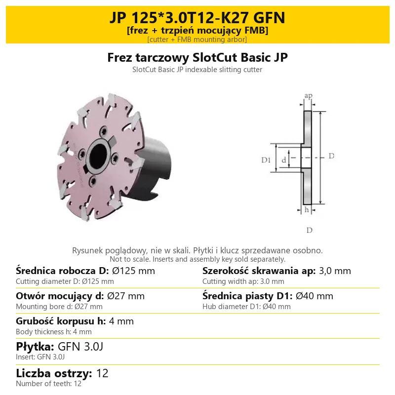
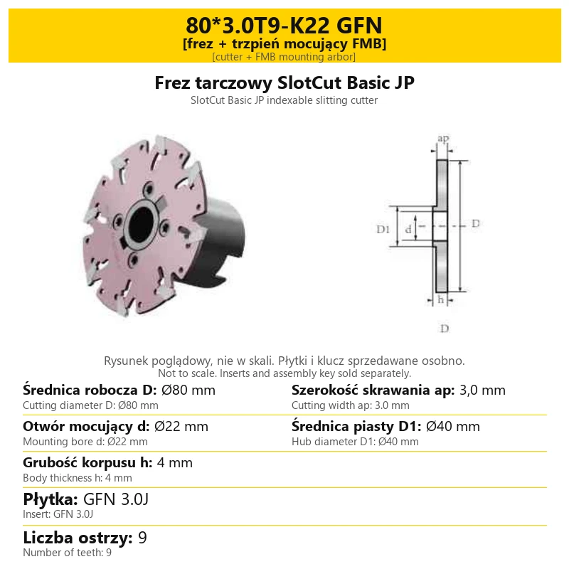
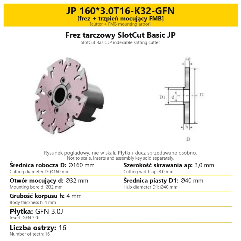
| Cutter + FMB mounting arbor | A cutter disc with a matched mounting arbor. | Cutting diameter D, width ap, bore d and assembly mounting. |
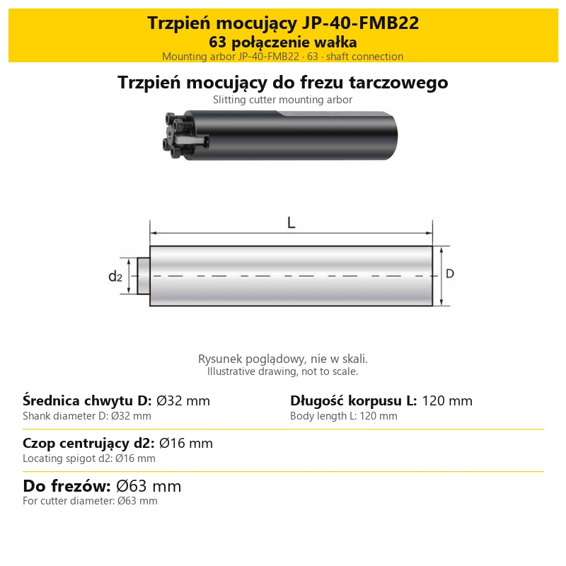
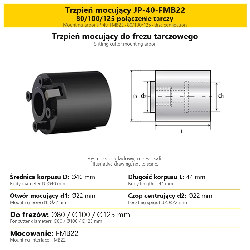
| Mounting arbor | A separate component connecting a suitable cutter disc to the holder. | Connection diameters and arbor length, not just cutter diameter. |
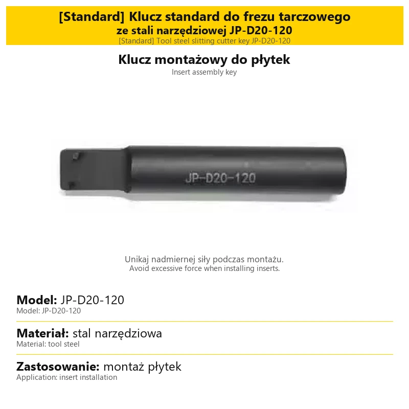
| Assembly key | A separate tool for installing inserts in their pockets. | The selected key type and its designation. |
Match the cylindrical shank to a suitable clamping holder, such as an ER holder. For a Weldon holder, check both the diameter and the clamping surface configuration of the specific shank. An FMB assembly and a cylindrical-shank cutter use different holder connections.
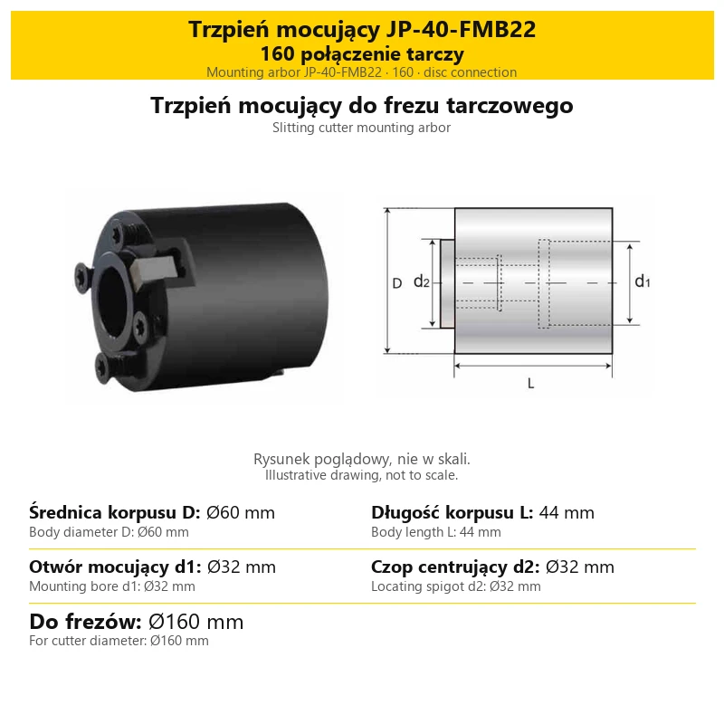
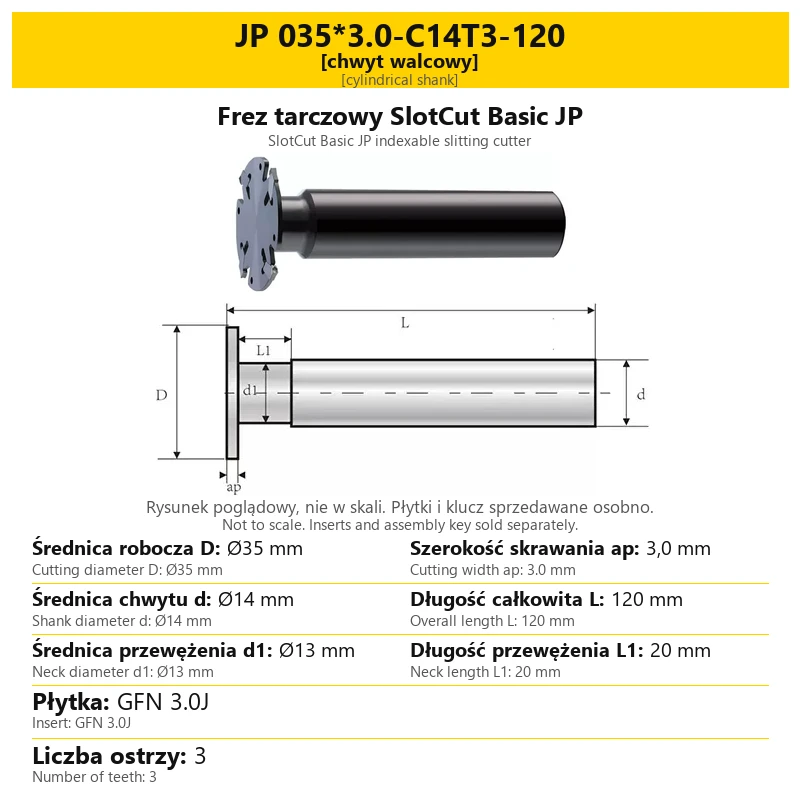
3. Technical drawing symbols
The drawing shows symbols; the table below gives the values in millimetres. Drawings are illustrative and must not be used to measure proportions. Read each symbol in the context of the component shown on that card.
| Symbol | Cylindrical-shank cutter | Cutter disc or arbor |
|---|---|---|
| D | Cutter cutting diameter. | On a disc card: cutting diameter. On an arbor card: body or shank diameter, as labelled. |
| ap | Cutting width. | Disc cutting width; different from diameter and body thickness h. |
| d | Cutter shank diameter. | On a disc card: mounting bore diameter. |
| L | Overall cutter length. | On an arbor card: the indicated body length. |
| d1 | Neck diameter behind the cutting head. | On a mounting module card: mounting bore diameter. |
| L1 | Neck length. | Shown on the cylindrical-shank cutter drawing. |
| D1 | — | On a disc card: hub diameter. |
| h | — | On a disc card: body thickness. |
| d2 | — | On an arbor card: locating spigot diameter. |
The Ø symbol means diameter. Neck dimensions d1 and L1 describe a different part of the tool from shank diameter d and overall length L. Do not interchange them when selecting a holder or checking available working space.
4. Reading the cutter designation
For example, JP 045*2.0-C20T4-120 identifies a cutter with a 45 mm cutting diameter, 2.0 mm cutting width, Ø20 mm shank, four teeth and 120 mm overall length.
| Code element | Meaning in the example |
|---|---|
| JP | Cutter series designation. |
| 045 | Ø45 mm cutting diameter. |
| 2.0 | 2.0 mm cutting width. |
| C20 | Ø20 mm cylindrical shank diameter. |
| T4 | Number of teeth: 4. |
| 120 | 120 mm overall length. |
Disc designations also include a bore code, such as K22 for a Ø22 mm bore. FMB identifies the mounting arrangement. Arbor codes are model designations: read their dimensions in the specific card table instead of transferring values from another component code.
5. Selecting cutting inserts
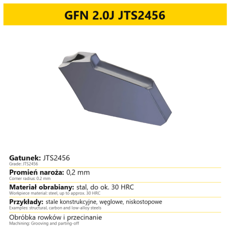
Match the insert to the cutting width and pocket of the selected cutter. The complete designation matters: similar codes do not necessarily identify the same fit. Each variant card states the primary insert type for that tool.
| Cutting width | Primary insert type | Compatible ISCAR designation |
|---|---|---|
| 2.0 mm | GFN 2.0J, grade JTS2456 | GFN 2J |
| 3.0 mm | GFN 3.0J, grade JTS2456 | GSFN 3 |
ISCAR GFN3, without the S in GSFN, is not compatible with this cutter. For the 3.0 mm configuration, distinguish the GFN 3.0J insert from its ISCAR GSFN 3 counterpart. The ISCAR insert grade is a separate element of its designation.
The number of teeth T specifies the number of inserts needed to populate the cutter. Inserts shown in illustrations demonstrate their position in the pockets; they are not included with the cutter body.
6. Arbors and mounting modules
Separately offered arbors have their own dimension cards. Compare the diameters of the components being connected. Matching the disc outside diameter alone does not confirm that its bore matches the arbor spigot.
| Arbor card parameter | Meaning for selection |
|---|---|
| Body or shank diameter D | Outside diameter of the indicated arbor section. |
| Body length L | Length indicated by dimension line L. |
| Mounting bore d1 | Bore diameter at the holder connection, where that bore is present in the module. |
| Locating spigot d2 | Diameter of the section that centres the cutter disc. |
| Listed cutter diameters | The model application designation; the actual connections still need to match. |
Before combining a disc with a separately purchased arbor, check the disc mounting bore and locating spigot diameter. A cylindrical arbor and a module with a mounting bore are different components; one component’s dimensions do not define the other’s.
7. Variant contents and assembly key
| Selected item | Contents |
|---|---|
| Cylindrical-shank cutter | Cutter body with shank. Inserts and the assembly key are purchased separately. |
| Cutter + FMB arbor | Cutter with the arbor specified in that variant. Inserts and the assembly key are purchased separately. |
| Separate arbor | The mounting component described and dimensioned on its card. |
| Standard key JP-D20-120 | Tool steel key for insert installation. |
| Premium key | Tool steel key with replaceable carbide pins. |
Use the appropriate key when seating inserts and avoid excessive force. Overloading or incorrect use can damage the key or insert; on the standard key, it can deform the pins. The Premium version has replaceable pins.
The key is not included in a cutter assembly. Select it as a separate item. Likewise, selecting a separate arbor does not mean purchasing a complete cutter.
8. Questions and answers
Are inserts and the key included?
No. They are sold separately from the cutter body or cutter-and-arbor assembly.
Do ap and h mean the same dimension?
No. ap is cutting width; h on a disc card is the cutter body thickness.
Does ISCAR GFN3 fit the 3.0 mm version?
No. The specified counterpart is ISCAR GSFN 3. The primary insert designation on the cutter card is GFN 3.0J.
How do I read dimensions when the drawing has only letters?
Find the same symbol in the table below the picture. Its full label is followed by the value in millimetres.
Is disc diameter enough to choose an arbor?
No. Also check the disc bore, locating spigot and arbor-to-holder connection. The selected component cards give these dimensions.
Related products
-
5BCB-19783

 Milling Inserts 0.00
GFN 2.0J 3.0J inserts replacement for ISCAR GFN 2J | ISCAR GSFN 3 (10 pcs.)
GFN 2.0J JTS2456 GFN 3.0J JTS2456 ISCAR GFN 2J IC328 ISCAR GSFN 3 IC908Price €60.40Price €49.11without VATShipping costs are not included in the price. -
98D8-1954A


SBL Disc Cutter for Slots - Disc Head, Radial R - Slot Tool
-
8D10-359E7

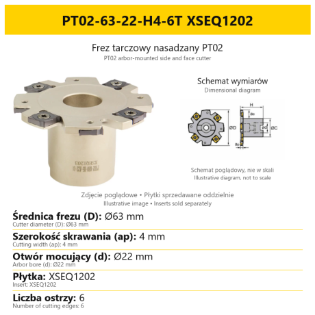
PT02 / SMA indexable side and face cutter for XSEQ inserts, Ø63–200 mm


Bestsellers
-
Bestseller
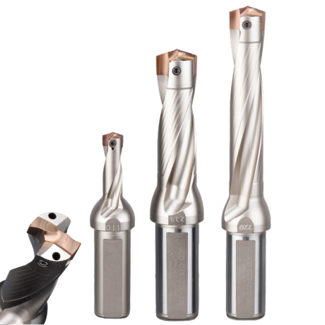
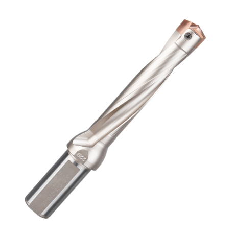
JCD modular drill with replaceable tip - internal cooling, for deep holes | GrotXD
JCD C20-100-3D Ø10~10.9 JCD C20-110-3D Ø11~11.9 JCD C20-120-3D Ø12~12.9 JCD C20-130-3D Ø13~13.9 JCD C20-140-3D Ø14~14.9 + 61 morePrice €69.52Price €56.52without VAT -
Price €17.09Price €13.90without VAT
-
Price €7.07Price €5.74without VAT
-
Price €7.52Price €6.12without VAT
-
Bestseller
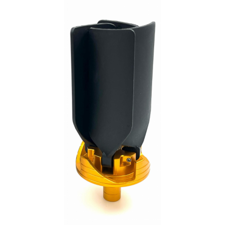
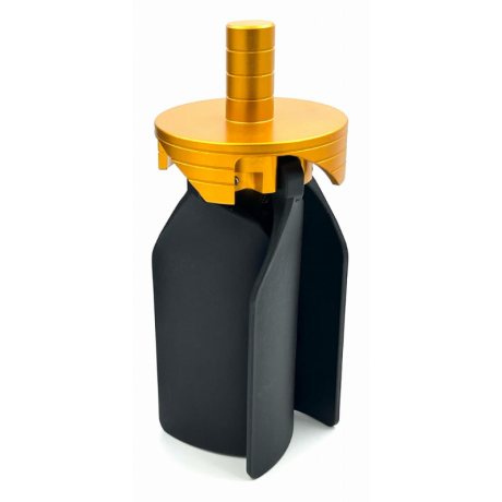 Other Accessories 0.00
CNC Chip Fan / Chip Blower
Complete CNC chip fan Kit: blades, springs, pins and screwsPrice €53.56Price €43.55without VAT -
Bestseller
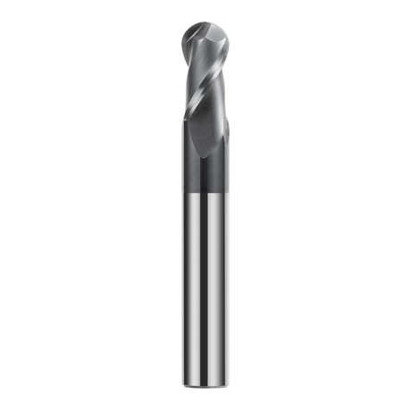
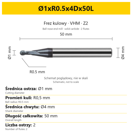 Ball Nose End Mills 0.00
2-Flute Carbide Ball Nose End Mill - HYPERCUT
Ø1xR0.5x4Dx50L Ø1.5xR0.75x4Dx50L Ø2xR1x4Dx50L Ø2.5xR1.25x4Dx50L Ø3xR1.5x3Dx50L + 26 morePrice €10.09Price €8.21without VAT -
Bestseller
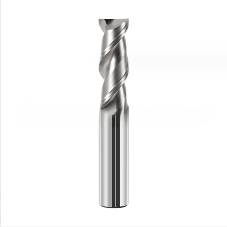
 2-Flute End Mills 0.00
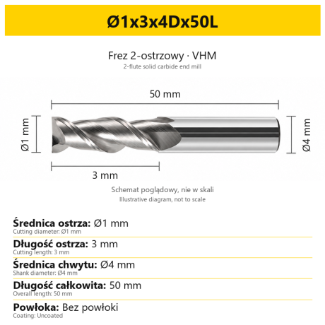
2-Flute Carbide End Mill for Aluminium
Ø1x3x4Dx50L Ø1.5x4x4Dx50L Ø2x6x4Dx50L Ø2.5x7.5x4Dx50L Ø3x9x3Dx50L + 31 morePrice €5.33Price €4.33without VAT -
Bestseller
 2-Flute End Mills 0.00
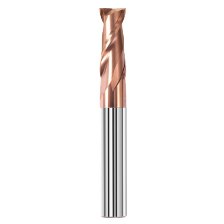
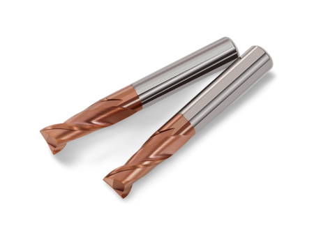
2-Flute Carbide End Mill for Steel 55 HRC - TiSiN - Solid Carbide
Ø6x24x6Dx75L Ø8x25x8Dx75L Ø4x20x4Dx100L Ø5x30x5Dx100L Ø6x30x6Dx100L + 31 morePrice €4.38Price €3.56without VAT -
Bestseller
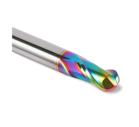 Ball Nose End Mills 0.00
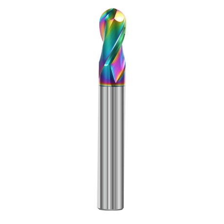
2-Flute DLC Coated Carbide Ball Nose End Mill| DuraEdge Alu
Ø1.0xR0.5x4Dx50L Ø1.5xR0.75x4Dx50L Ø2.0xR1x4Dx50L Ø2.5xR1.25x4Dx50L Ø3.0xR1.5x3Dx50L + 34 morePrice €7.85Price €6.38without VAT -
Bestseller
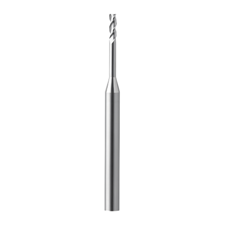
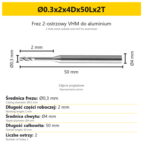 2-Flute End Mills 0.00
2-Flute End Mill for Aluminium | VHM | Miniature Ø0.3 - Ø0.9
Ø0.3x2x4Dx50Lx2T Ø0.3x3x4Dx50Lx2T Ø0.3x4x4Dx50Lx2T Ø0.4x2x4Dx50Lx2T Ø0.4x3x4Dx50Lx2T + 28 morePrice €7.95Price €6.47without VAT -
Bestseller
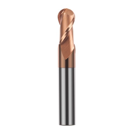
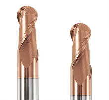 Ball Nose End Mills 0.00
2-Flute TiSiN Coated Carbide Ball Nose End Mill
Ø1xR0.5x4Dx50L Ø1.5xR0.75x4Dx50L Ø2xR1x4Dx50L Ø2.5xR1.25x4Dx50L Ø3xR1.5x3Dx50L + 38 morePrice €7.24Price €5.89without VAT -
Bestseller
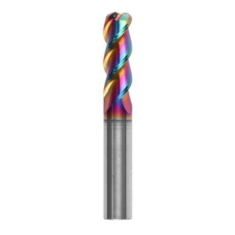
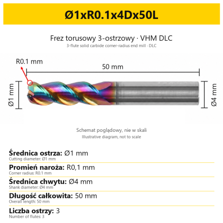
3-Flute Carbide Corner Radius End Mill for Aluminium| AL DLC
Ø1xR0.1x4Dx50L Ø1xR0.2x4Dx50L Ø1xR0.3x4Dx50L Ø1.5xR0.1x4Dx50L Ø1.5xR0.2x4Dx50L + 137 morePrice €5.89Price €4.79without VAT -
Bestseller
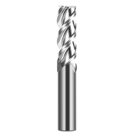
 3-Flute End Mills 0.00
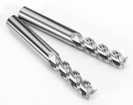
3-Flute Carbide End Mill VHM Z-3 for Aluminium| TriMill AL
Ø1x3xD4x50L Ø1.5x5x4Dx50L Ø2x6x4Dx50L Ø2.5x8x4Dx50L Ø3x9x3Dx50L + 41 morePrice €5.08Price €4.13without VAT -
Bestseller
 Countersinks 0.00
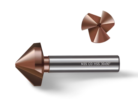
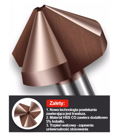
3-Flute Countersink Fi4.5-fi60, 90° - HSS-CO - 5% Kobaltu | Straight Shank
Ø4.5 x 4 x 90° x 40L Ø5 x 5 x 90° x 45L Ø6.3 x 5 x 90° x 45L Ø8.3 x 6 x 90° x 50L Ø10.4 x 6 x 90° x 50L + 12 morePrice €4.79Price €3.89without VAT -
Bestseller
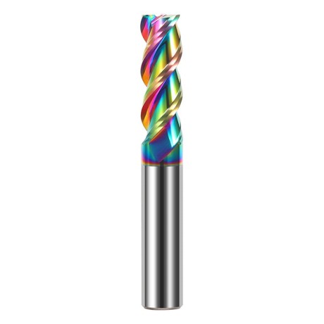 3-Flute End Mills 0.00
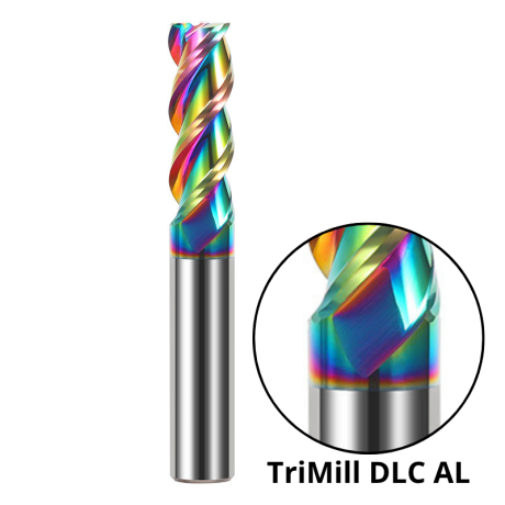
3-Flute DLC Coated Carbide End Mill | TriMill DLC AL
Ø1x3x4Dx50L Ø1.5x5x4Dx50L Ø2x6x4Dx50L Ø2.5x8x4Dx50L Ø3x8x3Dx50L + 38 morePrice €5.05Price €4.10without VAT -
Bestseller

 3-Flute End Mills 0.00
3-Flute HRC65 DLC Coated Carbide End Mill, U-Shaped Flute, for Aluminium | DuraEdge3 Alu
Ø1x3x4Dx50L Ø1.5x5x4Dx50L Ø2x6x4Dx50L Ø2.5x8x4Dx50L Ø3x9x3Dx50L + 40 morePrice €6.73Price €5.47without VAT