




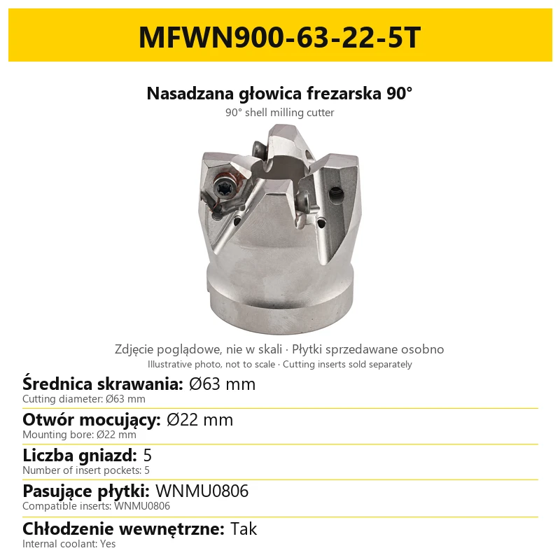


MFWN milling head for WNMU0806 inserts, clip-on shank, 90 degrees, without/with cooling
Shipping costs are not included in the price.
Shipping costs are not included in the price.
Ask about the product

The administrator of personal data is Kortools. We process it to respond to your inquiry. More information regarding the processing of personal data can be found in privacy policy.
Select a product variant:
Individual variants may differ in price
Product code: 00D3-1226F
Product description
Shell mounting • rough milling • versions without and with internal coolant
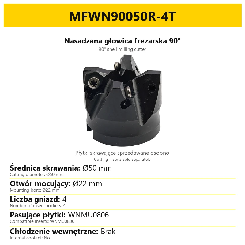
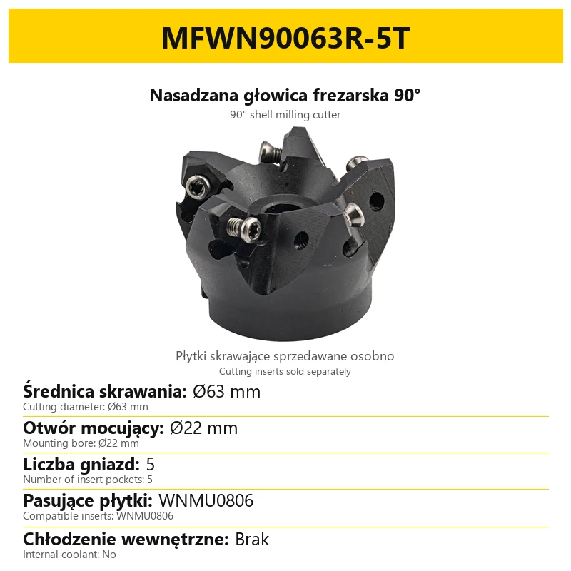
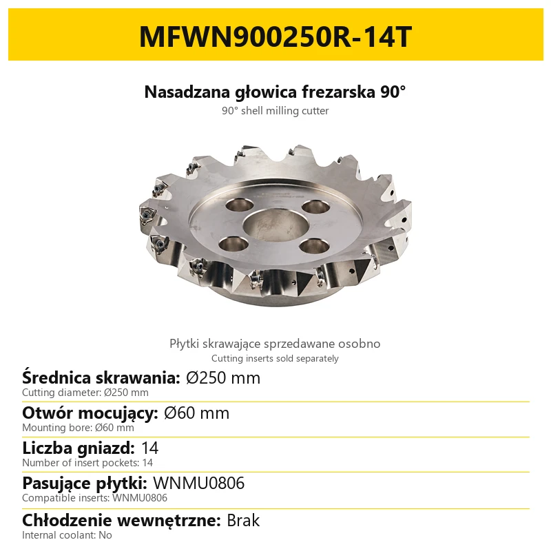
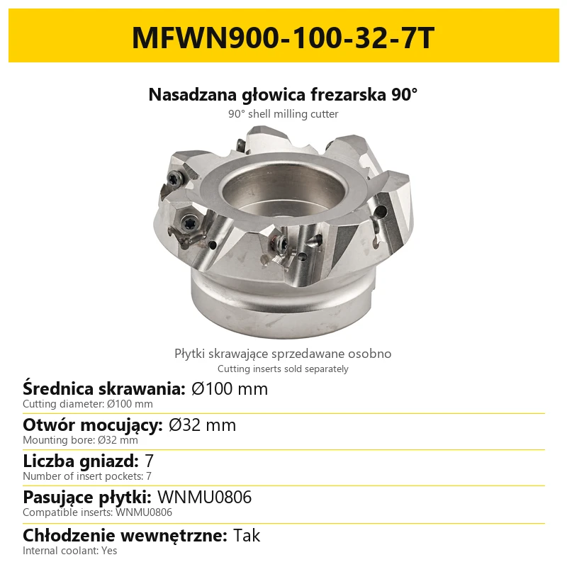
An MFWN shell milling cutter for rough machining, face milling, shoulder milling and rough side milling. The body takes replaceable inserts from the WNMU0806 family and has a 90° approach angle. Select the cutting diameter, number of insert pockets and coolant execution in the product variant selector.
The item sold is one cutter body without cutting inserts. Inserts are sold separately. Photographs with installed inserts show the assembled tool. Illustrative photographs represent the MFWN family; the selected variant designation and its information card state the specifications of that execution.
Applications
| Operation | Application |
|---|---|
| Rough machining | Material removal with a cutter equipped with replaceable WNMU0806 inserts. |
| Face milling | Machining flat surfaces with the assembled cutter. |
| Shoulder milling | Machining stepped surfaces with a 90° approach-angle cutter. |
| Side milling | Rough side milling within the limits of the cutter and selected inserts. |
The cutter is intended for carbon steel, stainless steel, cast iron and aluminium alloys with a suitable insert grade and cutting geometry. Choose the internal-coolant execution when the toolholder and machine can supply coolant through the tool.
Construction and insert system
The cutter uses double-sided WNMU0806 inserts with six cutting edges. Insert thickness is 8.5 mm. The working geometry of this system has a positive cutting angle. Inserts are secured by screws in pockets around the cutter body.
| Feature | Meaning |
|---|---|
| Shell-mounted body | The cutter fits a suitable milling arbor through its central mounting bore. |
| Insert pockets | Their number depends on the cutter variant and is indicated by the number before T. |
| Double-sided insert | Six cutting edges refers to one insert, not to the number of cutter pockets. |
| Screw clamping | Each insert is seated in its own pocket and secured with an insert screw. |
After one cutting edge wears, another edge of the same insert can be used. Machining suitability and cutting load also depend on the selected insert. Read the number of pockets from the variant designation separately from the number of usable edges on an individual insert.
Technical specifications
| Parameter | Specification |
|---|---|
| Approach angle | 90° |
| Insert system | WNMU0806 |
| Insert execution | Double-sided, six cutting edges |
| Insert thickness | 8.5 mm |
| Cutting diameters | Ø50–Ø315 mm, depending on execution |
| Number of insert pockets | 4–16, depending on variant |
| Cutter mounting | Shell mounting through a central bore |
| Mounting bores for the specified Ø50–Ø250 executions | Ø22, Ø27, Ø32, Ø40 or Ø60 mm, depending on cutter diameter |
| Internal coolant | Without or with internal coolant, according to the selected variant |
| Maximum depth of cut ap | 8 mm |
| Insert screw | M5x14 |
| Insert-screw tightening torque | Approximately 4.2 Nm |
| Unit of sale | 1 cutter body without cutting inserts |
The value ap = 8 mm is the stated maximum depth of cut for the cutter. It is not a universal setting for every operation. Match actual cutting conditions to the insert, workpiece material, tool diameter and setup. Mounting-bore dimensions refer to the body connection, not to the cutting diameter.
Body executions and mounting diameters
| Execution | Body material and hardness | Internal coolant |
|---|---|---|
| Standard Ø50–Ø250 | 42CrMoTi; body hardness 42–45 HRC | Without internal coolant |
| With internal coolant | SKD11; body hardness 45–48 HRC | Coolant passages within the cutter |
The HRC values above refer to the cutter body. They do not specify insert hardness or an allowable workpiece-hardness limit. The standard body is hardened and its surface is ground. The WNMU0806 insert system is common to both executions.
| Cutter cutting diameter | Mounting bore |
|---|---|
| Ø50 and Ø63 mm | Ø22 mm |
| Ø80 mm | Ø27 mm |
| Ø100 mm | Ø32 mm |
| Ø125 and Ø160 mm | Ø40 mm |
| Ø200 and Ø250 mm | Ø60 mm |
This table covers the specified Ø50–Ø250 executions. It does not specify the mounting bore of the Ø315 variant. Confirm the mounting connection when selecting a larger cutter for an arbor. Cutting diameter and mounting-bore diameter are different dimensions and cannot be used interchangeably.
How to read the variant designation
The designation identifies the MFWN family, cutting diameter and number of insert pockets. Internal-coolant designations also state the mounting-bore diameter. The selector retains the code format for each execution, and the corresponding card states the same specifications.
| Designation example | Meaning |
|---|---|
| MFWN900315R-16T | Cutting diameter Ø315 mm; 16 insert pockets; without internal coolant. |
| MFWN900-100-32-7T with coolant | Cutting diameter Ø100 mm; mounting bore Ø32 mm; 7 insert pockets; with internal coolant. |
The number before T is the number of insert pockets in the cutter. It is not the package quantity or the number of cutting edges on one insert. Linear dimensions are in millimetres. In particular, the Ø315 variant has 16 pockets, while each double-sided insert provides six cutting edges.
Mounting, inserts and working components
| Component | Specification | Purpose |
|---|---|---|
| Cutting inserts | WNMU0806; sold separately | Cutting elements seated in the body pockets. |
| Insert screws | M5x14 | Securing inserts in the pockets; tightening torque approximately 4.2 Nm. |
| Shell-mill arbor | Matched to the cutter mounting bore | Connecting the cutter to the machine toolholding system. |
When choosing an arbor, check the mounting bore of the selected body. When choosing an insert, check the WNMU0806 family, grade and cutting geometry for the workpiece material and operation. A photograph showing fitted inserts does not mean that inserts are supplied with the cutter.
Approximately 4.2 Nm applies to the screw securing the insert. It is not the tightening torque for securing the complete cutter to the arbor. The cutter-to-arbor connection has its own mounting requirements.
Selecting a cutter for the operation
- Select the cutting diameter to suit the surface and planned operation.
- Match the mounting connection by checking the central bore and corresponding arbor.
- Select the coolant execution to suit the planned coolant-supply arrangement.
- Select WNMU0806 inserts by workpiece material, insert grade and cutting geometry.
- Select cutting conditions for the assembled cutter, taking account of diameter, pocket count and the maximum depth of cut ap = 8 mm.
An illustrative photograph shows the family construction. Select dimensions and pocket count from the variant designation and its information card. Where executions share the same diameter, also check the number before T and the internal-coolant information.
Frequently asked questions
Are inserts included?
No. The item sold is one cutter body. WNMU0806 inserts are sold separately, including when they are shown in a photograph.
Does 16T mean sixteen edges on one insert?
No. It means sixteen insert pockets in the body. Six cutting edges refers to one double-sided insert.
Does the Ø315 variant have internal coolant?
The Ø315 execution with 16 pockets is without internal coolant. Internal-coolant variants are separately identified in the selector.
Do all cutters have the same mounting bore?
No. The specified Ø50–Ø250 executions use Ø22, Ø27, Ø32, Ø40 or Ø60 mm bores, depending on diameter. Confirm the Ø315 mounting connection before selecting an arbor.
What do the 42–45 and 45–48 HRC values refer to?
The body hardness of the corresponding cutter execution, not the hardness of the workpiece.
Product safety
Responsible person in the EU
Kamil Henkelman
TYSIĄCLECIA, 41B
41-933 Bytom, Poland
Related products
-
F864-14262


Milling head LN11 / LN15 for LNPU110408 / LNPU150408 inserts | 90° | FMB clip-on grip | 42CrMo | Side wall finishing | With internal cooling l/without cooling
-
F7CD-54958Bestseller


LN11 milling head for LNPU110408 inserts | 90 degrees | Cylindrical shank | 42CrMo | Side wall finishing | without cooling | with internal cooling
-
89A5-76271Bestseller


BAP300R BAP400R milling head for APKT/APMT inserts
-
95FF-903C4Bestseller

 Face Milling Heads 4.43
MFPN66 planning head for inserts PNMU090508 - FMB clip-on holder
-
F5CB-213DABestseller


High Feed head - EXN03R for LNMU0303 inserts - FMB clip-on shank
-
95FF-903C5

 Face Milling Heads 0.00
MFPN66 planning head with internal cooling for inserts PNMU090508 - FMB push-on holder


Bestsellers
-
Bestseller
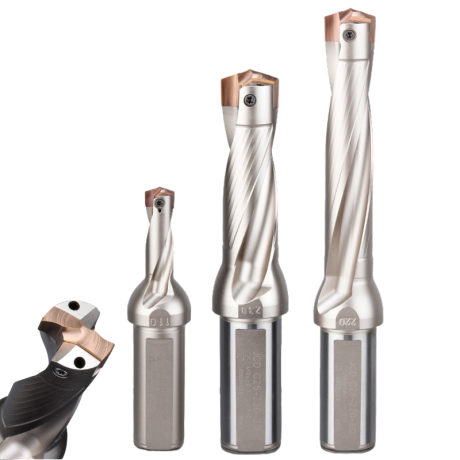
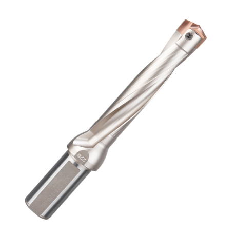
JCD modular drill with replaceable tip - internal cooling, for deep holes | GrotXD
JCD C20-100-3D Ø10~10.9 JCD C20-110-3D Ø11~11.9 JCD C20-120-3D Ø12~12.9 JCD C20-130-3D Ø13~13.9 JCD C20-140-3D Ø14~14.9 + 61 morePrice €69.86Price €56.79without VAT -
Bestseller
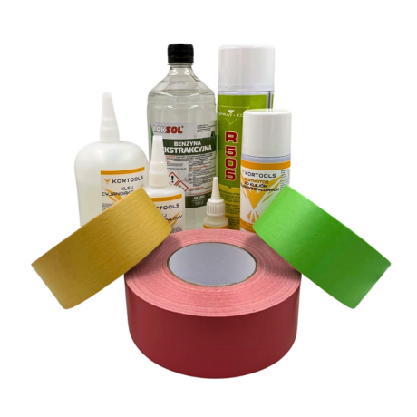
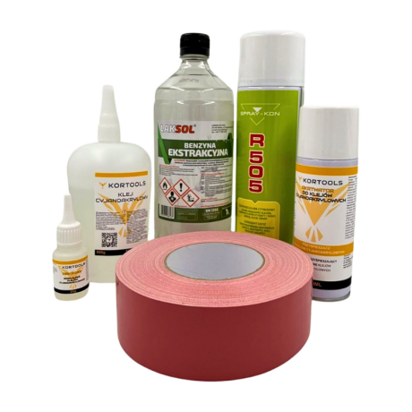
Kortools Adhesive + Tape CNC Workholding Kit
Yellow tape 5cm x 50m; adhesive 100g Yellow tape 5cm x 50m; adhesive 500g Yellow tape 10cm x 50m; adhesive 100g Yellow tape 10cm x 50m; adhesive 500g Green tape 5cm x 50m; adhesive 100g + 7 morePrice €44.66Price €36.31without VAT -
Price €17.18Price €13.97without VAT
-
Price €7.10Price €5.77without VAT
-
Price €7.56Price €6.14without VAT
-
Bestseller
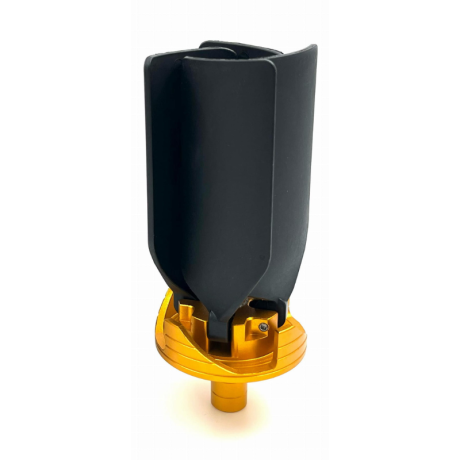
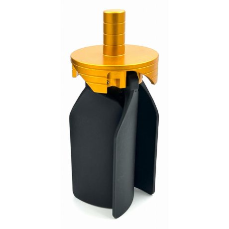 Other Accessories 0.00
CNC Chip Fan / Chip Blower
Complete CNC chip fan Kit: blades, springs, pins and screwsPrice €53.82Price €43.76without VAT -
Bestseller
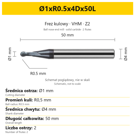 Ball Nose End Mills 0.00
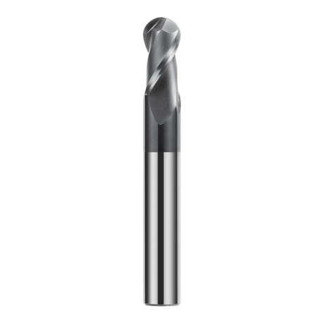
2-Flute Carbide Ball Nose End Mill - HYPERCUT
Ø1xR0.5x4Dx50L Ø1.5xR0.75x4Dx50L Ø2xR1x4Dx50L Ø2.5xR1.25x4Dx50L Ø3xR1.5x3Dx50L + 26 morePrice €10.14Price €8.25without VAT -
Bestseller
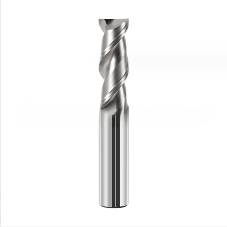
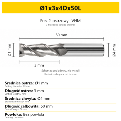 2-Flute End Mills 0.00
2-Flute Carbide End Mill for Aluminium
Ø1x3x4Dx50L Ø1.5x4x4Dx50L Ø2x6x4Dx50L Ø2.5x7.5x4Dx50L Ø3x9x3Dx50L + 31 morePrice €5.35Price €4.35without VAT -
Bestseller
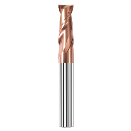
 2-Flute End Mills 0.00
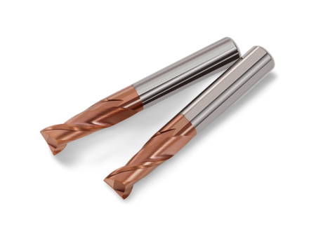
2-Flute Carbide End Mill for Steel 55 HRC - TiSiN - Solid Carbide
Ø6x24x6Dx75L Ø8x25x8Dx75L Ø4x20x4Dx100L Ø5x30x5Dx100L Ø6x30x6Dx100L + 31 morePrice €4.40Price €3.58without VAT -
Bestseller
 Ball Nose End Mills 0.00
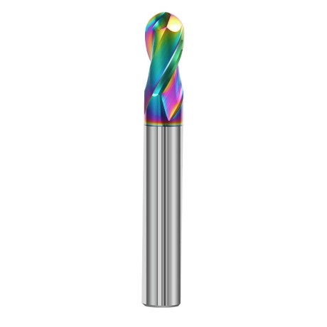
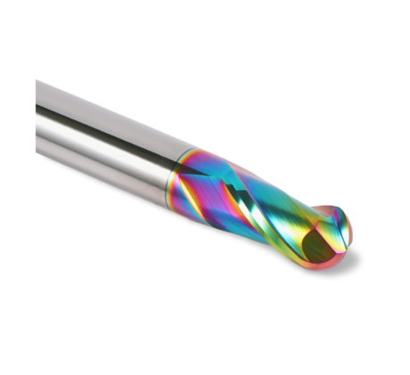
2-Flute DLC Coated Carbide Ball Nose End Mill| DuraEdge Alu
Ø1.0xR0.5x4Dx50L Ø1.5xR0.75x4Dx50L Ø2.0xR1x4Dx50L Ø2.5xR1.25x4Dx50L Ø3.0xR1.5x3Dx50L + 34 morePrice €7.89Price €6.41without VAT -
Bestseller
 2-Flute End Mills 0.00
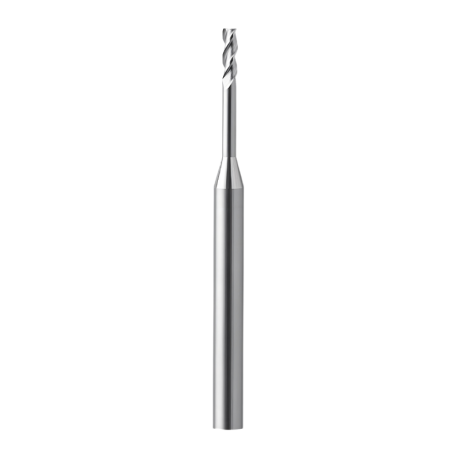
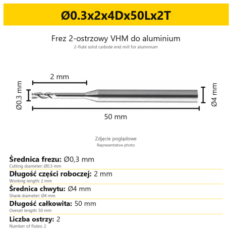
2-Flute End Mill for Aluminium | VHM | Miniature Ø0.3 - Ø0.9
Ø0.3x2x4Dx50Lx2T Ø0.3x3x4Dx50Lx2T Ø0.3x4x4Dx50Lx2T Ø0.4x2x4Dx50Lx2T Ø0.4x3x4Dx50Lx2T + 28 morePrice €7.99Price €6.50without VAT -
Bestseller
 Ball Nose End Mills 0.00
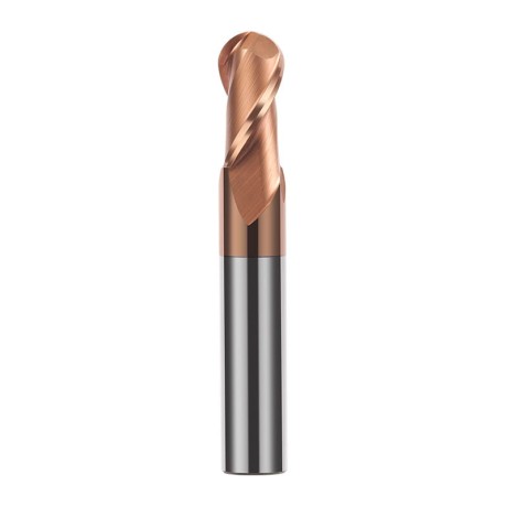
2-Flute TiSiN Coated Carbide Ball Nose End Mill
Ø1xR0.5x4Dx50L Ø1.5xR0.75x4Dx50L Ø2xR1x4Dx50L Ø2.5xR1.25x4Dx50L Ø3xR1.5x3Dx50L + 38 morePrice €7.28Price €5.92without VAT -
Bestseller
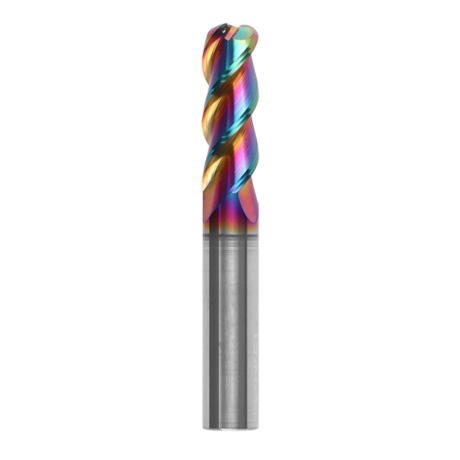
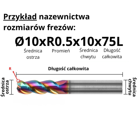
3-Flute Carbide Corner Radius End Mill for Aluminium| AL DLC
Ø1xR0.1x4Dx50L Ø1xR0.2x4Dx50L Ø1xR0.3x4Dx50L Ø1.5xR0.1x4Dx50L Ø1.5xR0.2x4Dx50L + 137 morePrice €4.96Price €4.04without VAT -
Bestseller
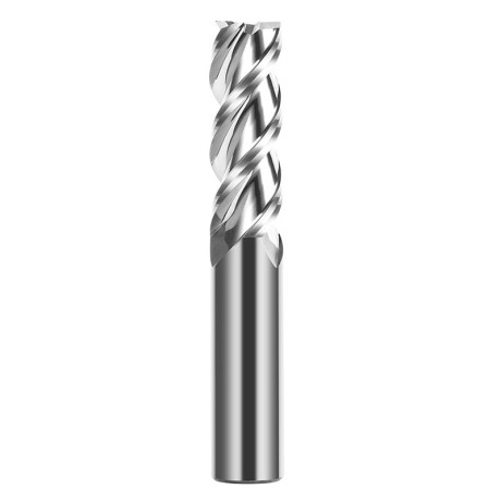
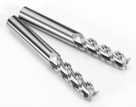 3-Flute End Mills 0.00
3-Flute Carbide End Mill VHM Z-3 for Aluminium| TriMill AL
Ø1x3xD4x50L Ø1.5x5x4Dx50L Ø2x6x4Dx50L Ø2.5x8x4Dx50L Ø3x9x3Dx50L + 41 morePrice €5.10Price €4.15without VAT -
Bestseller
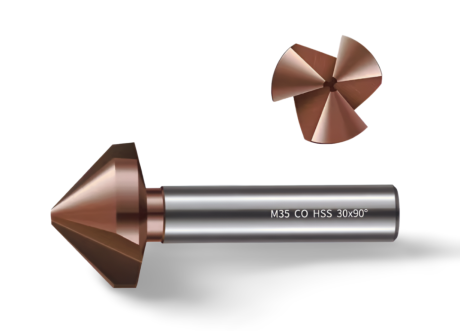
 Countersinks 0.00
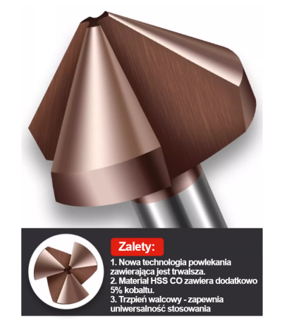
3-Flute Countersink Fi4.5-fi60, 90° - HSS-CO - 5% Kobaltu | Straight Shank
Ø4.5 x 4 x 90° x 40L Ø5 x 5 x 90° x 45L Ø6.3 x 5 x 90° x 45L Ø8.3 x 6 x 90° x 50L Ø10.4 x 6 x 90° x 50L + 12 morePrice €4.81Price €3.91without VAT -
Bestseller
 3-Flute End Mills 0.00
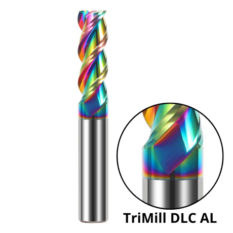
3-Flute DLC Coated Carbide End Mill | TriMill DLC AL
Ø1x3x4Dx50L Ø1.5x5x4Dx50L Ø2x6x4Dx50L Ø2.5x8x4Dx50L Ø3x8x3Dx50L + 38 morePrice €5.07Price €4.12without VAT