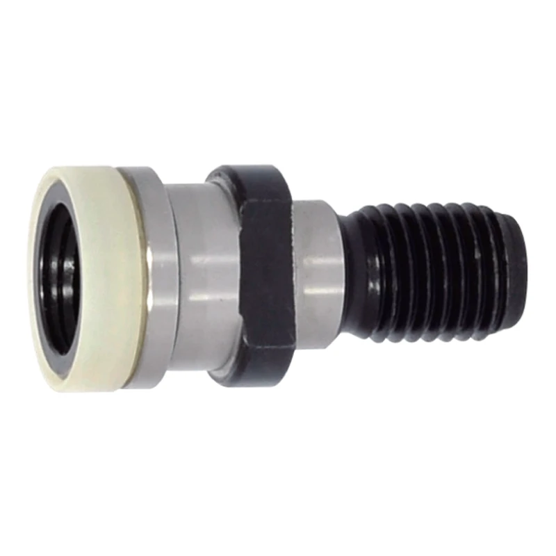
OTT40/OTT50 pull stud (retention knob), M16/M24 thread
Shipping costs are not included in the price.
Shipping costs are not included in the price.
Ask about the product

The administrator of personal data is Kortools. We process it to respond to your inquiry. More information regarding the processing of personal data can be found in privacy policy.
Select a product variant:
Individual variants may differ in price
Product code: 8045-7E52E
Product description
1. OTT mechanism and the complete part profile
OTT identifies a separate gripping mechanism. External gripping-end dimensions and thread do not specify its complete internal geometry. Selection requires the profile to be compared with the spindle mechanism requirements.
This description presents nominal OTT40 and OTT50 references, not measurements of a specific part. Holder size or a similar diameter alone does not justify substituting pull studs.
2. OTT and the DIN 2080 designation
DIN 2080-1 concerns the taper tool shank. It does not independently establish a standard for an OTT pull stud or specify the complete internal gripping-end geometry.
Distinguish holder designation, pull-stud geometry and gripping-mechanism requirements. A thread that fits the holder does not replace checking the other mating surfaces.
3. Nominal OTT40 and OTT50 dimensions
Lengths and diameters in the table are nominal millimetre values. M retains the published thread designation without an added pitch or tolerance. Compare the data with the complete drawing of the required part.
| Reference profile | M | d1 [mm] | d2 [mm] | d3 [mm] | d4 [mm] | L3 [mm] | L2 [mm] | L1 [mm] |
|---|---|---|---|---|---|---|---|---|
| OTT40 | M16 | 25 | 21.1 | 17 | 7 | 13.6 | 25.1 | 53 |
| OTT50 | M24 | 39.6 | 30.2 | 25 | 7 | 13.3 | 25.1 | 65.1 |
d1/d2/d3/d4 belong to this OTT profile. Do not transfer their meanings from a conventional SK or BT knob drawing. External dimensions do not establish the internal thread or the function of a visible opening.
4. L1, L2, L3 and the other symbols
| Symbol | Meaning in this OTT profile |
|---|---|
| d1 | Outside diameter of gripping end |
| d2 | Diameter behind gripping end |
| d3 | Pilot diameter beside thread |
| d4 | Dimension of axial feature in drawing |
| L1 | Overall length |
| L2 | Gripping-end face → support plane |
| L3 | Rear of gripping end → support plane |
L1 is the overall length here, not a head-to-flange distance. L2 runs from the gripping-end face to the support plane, and L3 from its rear boundary to that plane. None of these descriptions automatically defines thread length.
d1 is the gripping-end outside dimension, d2 the dimension behind it and d3 the pilot beside the thread. d4 remains a drawing dimension of an axial feature; it does not specify a thread or the complete internal shape.
5. Identify internal grip and thread separately
A large visible opening does not specify the complete internal grip. It cannot establish internal-thread pitch, class or hand, gripping surfaces or their depth.
M16 and M24 in column M do not specify every internal feature. Do not apply them to an unspecified internal thread. Compare the contact geometry with the requirements of the particular mechanism.
The table does not state a numerical gripping-surface angle. Do not adopt an angle from another profile merely because its length or diameter is similar.
6. Passage and sealing as separate features
The nominal d4 = 7 mm belongs to a feature marked in the drawing. It does not establish coolant continuity, an internal thread or the function of the large gripping-end opening.
A through passage connects both ends of the part; a blind bore ends inside it. A visible inlet does not establish the path. A part without a through passage may have another bore or recess.
O-ring presence, number and position, and the sealing contact location require separate identification. A ring does not prove a through passage, and an opening does not specify sealing.
7. Comparing the part required by the spindle
Start with the complete drawing of the part required by the mechanism. Compare:
- The profile and mating gripping surfaces, including the internal surfaces.
- The thread with its required pitch and type.
- d1/d2/d3 and the local d4 feature in the correct drawing.
- The overall length L1 and L2/L3 distances between the specified faces.
- The passage path and separate sealing requirements.
OTT40/OTT50, DIN 2080 or M16 alone do not establish interchangeability. Nominal dimensions do not specify composition, tightening torque or the properties of a particular part.
8. Short FAQ
Is DIN 2080 a standard for this pull stud?
Do not infer that from the holder name. DIN 2080-1 describes the tool shank; compare the OTT profile separately.
Is L1 the thread length?
No. L1 is the overall length in this reference.
Does d4 = 7 mm establish a through passage?
No. It is a nominal drawing feature, without specifying the internal path or function.
Does the large opening specify the internal thread?
No. Its full designation and gripping geometry require a separate specification.
Related pull studs and tool holders
Compare pull stud families. The holder and stud must match the specific spindle, head profile, thread, length, bore and seal.
Other pull stud families
- BT30/BT40/BT45/BT50 pull stud (retention knob), 45°/60°/90°, through or non-through, with O-ring / without O-ring
- DIN 69872 SK30/SK40/SK50 pull stud (retention knob), through or non-through, with O-ring / without O-ring
- Pull stud (retention knob) for Haas SK40/SK50, M16/M24 thread
- ISO7388 A/B 30/40/45/50 pull stud (retention knob), M12/M16/M20/M24 thread
- CAT30/CAT40/CAT45/CAT50 pull stud (retention knob), inch thread
- ISO20/ISO25/ISO30 pull stud (retention knob), M8/M12 thread
- Pull stud (retention knob) for Mazak BT40/BT50, M16/M24 thread, C/CO
- Pull stud (retention knob) for Mazak CAT40/CAT50, M16/M24 metric thread
- JIS 30P/35P/40P/45P/50P/55P pull stud (retention knob)
Tool holders
Related products
-
C74F-C524A
 Pull Studs 0.00
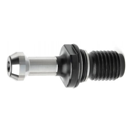
BT30/BT40/BT45/BT50 pull stud (retention knob) for JIS B 6339 tool holders, 45°/60°/90°, through and non-through variants, variants with O-ring
BT30-45, for JIS B 6339 holders - non-through, M12, L43 mm, angle 45° BT30-60, for JIS B 6339 holders - non-through, M12, L43 mm, angle 60° BT30-90, for JIS B 6339 holders - non-through, M12, L43 mm, angle 90° BT30C-45, for JIS B 6339 holders - through bore, M12, L43 mm, angle 45° BT30C-60, for JIS B 6339 holders - through bore, M12, L43 mm, angle 60° + 31 morePrice €3.66Price €2.98without VATShipping costs are not included in the price. -
2436-AE53C
 Pull Studs 0.00
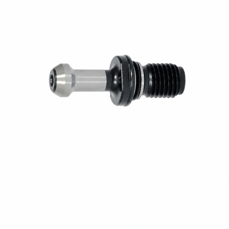
SK30/SK40/SK50 pull stud (retention knob), DIN 69872 profile, for DIN 69871 tool holders, through and non-through variants, variants with O-ring
SK40-BO, DIN 69872 - non-through, with O-ring, M16, L54 mm SK50-A, DIN 69872 - through bore, M24, L74 mm SK50-AO, DIN 69872 - through bore, with O-ring, M24, L74 mm SK50-B, DIN 69872 - non-through, M24, L74 mm SK50-BO, DIN 69872 - non-through, with O-ring, M24, L74 mm + 6 morePrice €4.92Price €4.00without VATShipping costs are not included in the price. -
C3A6-6D925
 Pull Studs 0.00
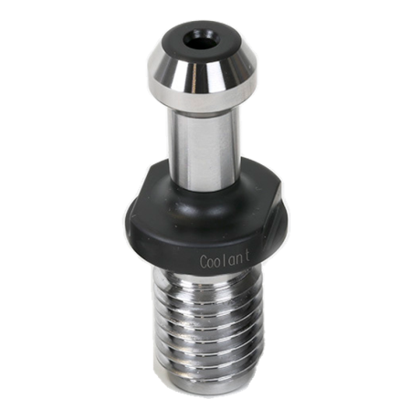
Haas SK40/SK50 pull stud (retention knob) for DIN 69871 tool holders, M16/M24 thread, through-bore and O-ring variants
Haas SK40, for DIN 69871 holders - through bore, M16×2.0, L57.15 mm, angle 45° Haas SK50, for DIN 69871 holders - M24×3.0, L85.05 mm, angle 45° Haas SK40, for DIN 69871 holders - through bore, with O-ring, M16×2.0, L57.15 mm, angle 45°Price €5.70Price €4.64without VATShipping costs are not included in the price. -
3D23-1A5A9
 Pull Studs 0.00
Pull stud (retention knob) for DIN 69871 tool holders, ISO 7388 A/B profiles 30/40/45/50, through bore variants
ISO7388-40A, for DIN 69871 holders - through bore, M16, L54 mm ISO7388-50A, for DIN 69871 holders - through bore, M24, L74 mm ISO7388-40B, for DIN 69871 holders - through bore, M16, L44.4 mm ISO7388-50B, for DIN 69871 holders - through bore, M24, L66.55 mm ISO7388-30A, for DIN 69871 holders - M12, L44 mm, angle 15° + 3 morePrice €5.24Price €4.26without VATShipping costs are not included in the price. -
D8B1-01BFC
 Pull Studs 0.00
CAT30/CAT40/CAT45/CAT50 pull stud (retention knob) for ANSI/ASME B5.50 tool holders, inch thread, through bore variants
CAT40-A, for ANSI/ASME B5.50 holders - through bore, 5/8"-11, L38.1 mm, angle 45° CAT50-A, for ANSI/ASME B5.50 holders - through bore, 1"-8, L58.42 mm, angle 45° BT-CAT40-45C, for ANSI/ASME B5.50 holders - 5/8"-11, angle 45° BT-CAT50-90C, for ANSI/ASME B5.50 holders - 1"-8, angle 90° CAT30, for ANSI/ASME B5.50 holders - through bore, 1/2"-13, L27.94 mm, angle 45° + 1 morePrice €5.70Price €4.64without VATShipping costs are not included in the price. -
6A89-FD6D2
 Pull Studs 0.00
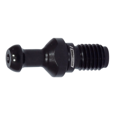
ISO20/ISO25/ISO30 pull stud (retention knob), M8/M12 thread
ISO20 - M8, L26 mm ISO25 - M8, L28 mm ISO30 - M12, L44 mmPrice €4.10Price €3.33without VATShipping costs are not included in the price. -
81A7-7A6D8
 Pull Studs 0.00
Mazak BT40/BT50 pull stud (retention knob) for JIS B 6339 tool holders, M16/M24 thread, C/CO, through bore
Mazak BT40 C, for JIS B 6339 holders - through bore, M16, L44.1 mm, angle 45° Mazak BT50 C, for JIS B 6339 holders - through bore, M24, L65.2 mm, angle 45° Mazak BT40 CO, for JIS B 6339 holders - through bore, M16, L44.1 mm, angle 45° Mazak BT50 CO, for JIS B 6339 holders - through bore, M24, L65.2 mm, angle 45°Price €7.99Price €6.50without VATShipping costs are not included in the price. -
B9B8-A4C23
 Pull Studs 0.00
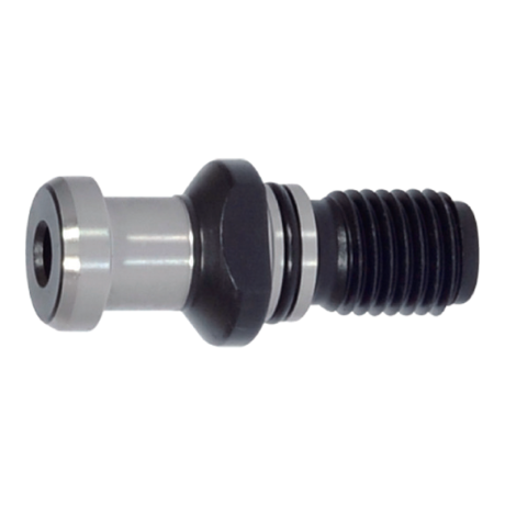
Mazak CAT40/CAT50 pull stud (retention knob), M16/M24 metric thread
Mazak-CAT40 - M16, L41.25 mm, angle 45° Mazak-CAT50 - M24, L65.4 mm, angle 45°Price €7.99Price €6.50without VATShipping costs are not included in the price. -
3578-7E58B
 Pull Studs 0.00
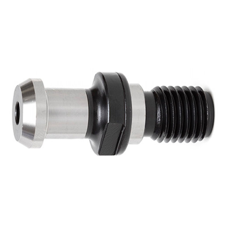
JIS B 6339 pull stud (retention knob), profiles 30P/35P/40P/45P/50P/55P, through bore
JIS-30P, JIS B 6339 - through bore, M12, L43 mm JIS-35P, JIS B 6339 - through bore, M12, L44 mm JIS-40P, JIS B 6339 - through bore, M16, L54 mm JIS-45P, JIS B 6339 - through bore, M20, L60 mm JIS-50P, JIS B 6339 - through bore, M24, L74 mm + 1 morePrice €4.92Price €4.00without VATShipping costs are not included in the price.


Bestsellers
-
Bestseller
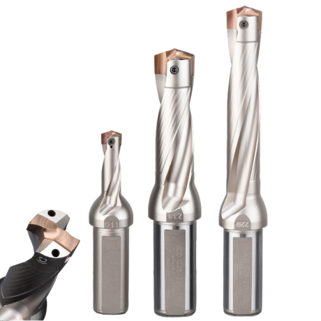
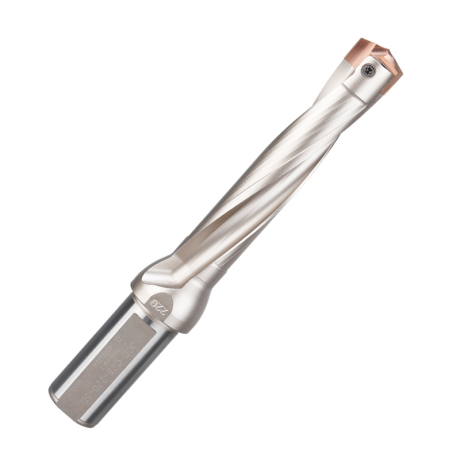
JCD modular drill with replaceable tip - internal cooling, for deep holes | GrotXD
JCD C20-100-3D Ø10~10.9 JCD C20-110-3D Ø11~11.9 JCD C20-120-3D Ø12~12.9 JCD C20-130-3D Ø13~13.9 JCD C20-140-3D Ø14~14.9 + 61 morePrice €69.86Price €56.79without VAT -
Bestseller
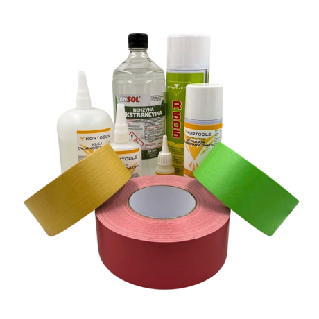
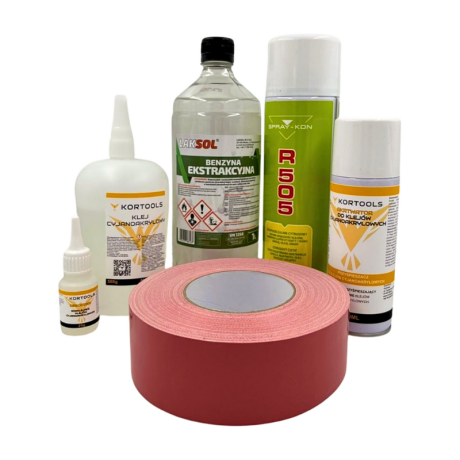
Kortools Adhesive + Tape CNC Workholding Kit
Yellow tape 5cm x 50m; adhesive 100g Yellow tape 5cm x 50m; adhesive 500g Yellow tape 10cm x 50m; adhesive 100g Yellow tape 10cm x 50m; adhesive 500g Green tape 5cm x 50m; adhesive 100g + 7 morePrice €44.66Price €36.31without VAT -
Price €17.18Price €13.97without VAT
-
Price €7.10Price €5.77without VAT
-
Price €7.56Price €6.14without VAT
-
Bestseller
 Other Accessories 0.00
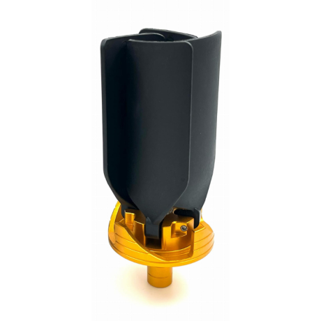
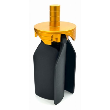
CNC Chip Fan / Chip Blower
Complete CNC chip fan Kit: blades, springs, pins and screwsPrice €53.82Price €43.76without VAT -
Bestseller
 Ball Nose End Mills 0.00
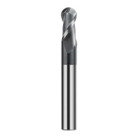
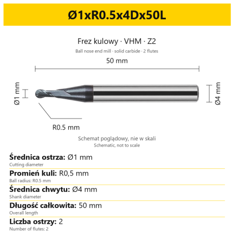
2-Flute Carbide Ball Nose End Mill - HYPERCUT
Ø1xR0.5x4Dx50L Ø1.5xR0.75x4Dx50L Ø2xR1x4Dx50L Ø2.5xR1.25x4Dx50L Ø3xR1.5x3Dx50L + 26 morePrice €10.14Price €8.25without VAT -
Bestseller
 2-Flute End Mills 0.00
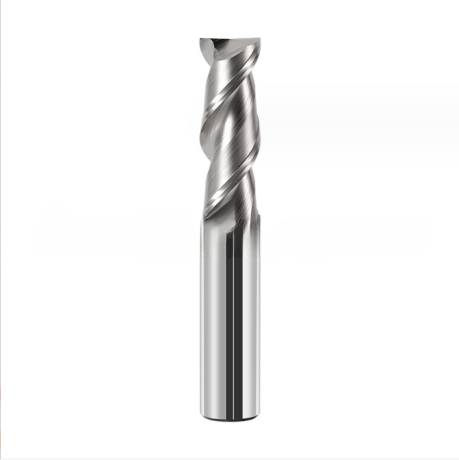
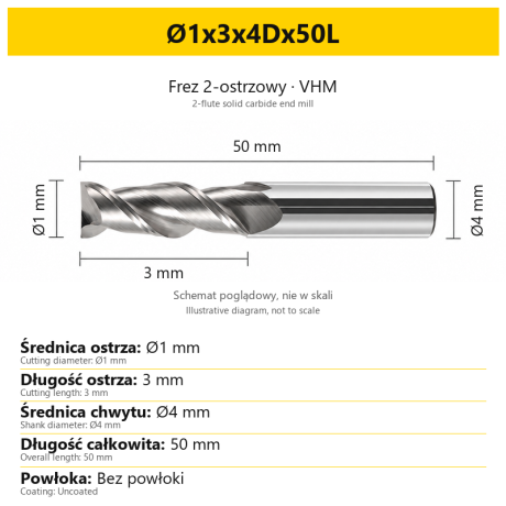
2-Flute Carbide End Mill for Aluminium
Ø1x3x4Dx50L Ø1.5x4x4Dx50L Ø2x6x4Dx50L Ø2.5x7.5x4Dx50L Ø3x9x3Dx50L + 31 morePrice €5.35Price €4.35without VAT -
Bestseller
 2-Flute End Mills 0.00
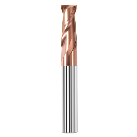
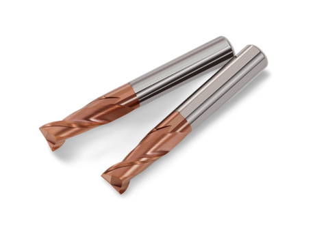
2-Flute Carbide End Mill for Steel 55 HRC - TiSiN - Solid Carbide
Ø6x24x6Dx75L Ø8x25x8Dx75L Ø4x20x4Dx100L Ø5x30x5Dx100L Ø6x30x6Dx100L + 31 morePrice €4.40Price €3.58without VAT -
Bestseller
 Ball Nose End Mills 0.00
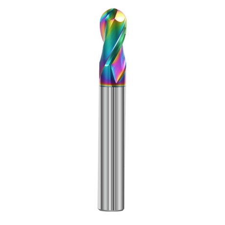
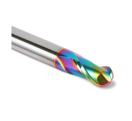
2-Flute DLC Coated Carbide Ball Nose End Mill| DuraEdge Alu
Ø1.0xR0.5x4Dx50L Ø1.5xR0.75x4Dx50L Ø2.0xR1x4Dx50L Ø2.5xR1.25x4Dx50L Ø3.0xR1.5x3Dx50L + 34 morePrice €7.89Price €6.41without VAT -
Bestseller
 2-Flute End Mills 0.00
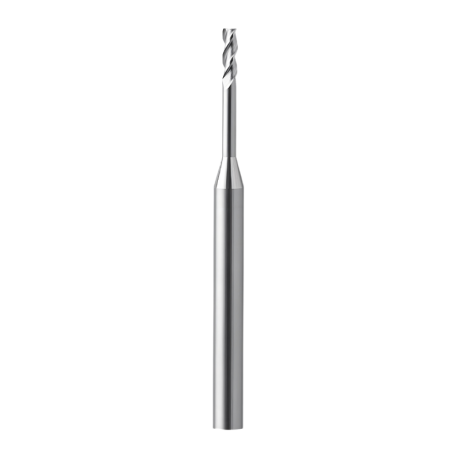
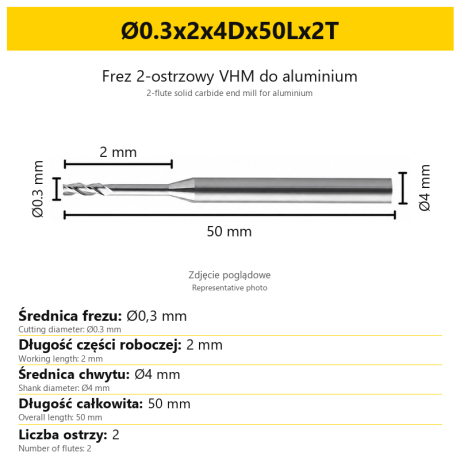
2-Flute End Mill for Aluminium | VHM | Miniature Ø0.3 - Ø0.9
Ø0.3x2x4Dx50Lx2T Ø0.3x3x4Dx50Lx2T Ø0.3x4x4Dx50Lx2T Ø0.4x2x4Dx50Lx2T Ø0.4x3x4Dx50Lx2T + 28 morePrice €7.99Price €6.50without VAT -
Bestseller
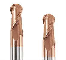 Ball Nose End Mills 0.00
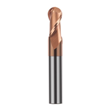
2-Flute TiSiN Coated Carbide Ball Nose End Mill
Ø1xR0.5x4Dx50L Ø1.5xR0.75x4Dx50L Ø2xR1x4Dx50L Ø2.5xR1.25x4Dx50L Ø3xR1.5x3Dx50L + 38 morePrice €7.28Price €5.92without VAT -
Bestseller
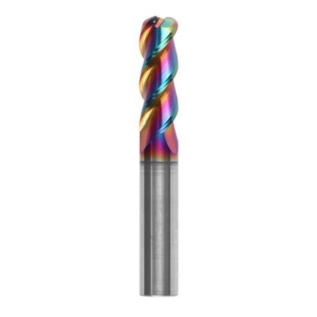
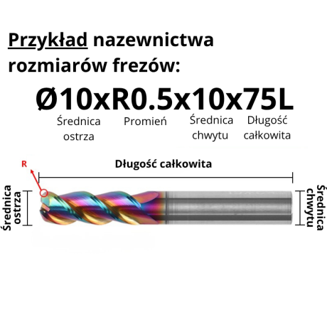
3-Flute Carbide Corner Radius End Mill for Aluminium| AL DLC
Ø1xR0.1x4Dx50L Ø1xR0.2x4Dx50L Ø1xR0.3x4Dx50L Ø1.5xR0.1x4Dx50L Ø1.5xR0.2x4Dx50L + 137 morePrice €4.96Price €4.04without VAT -
Bestseller
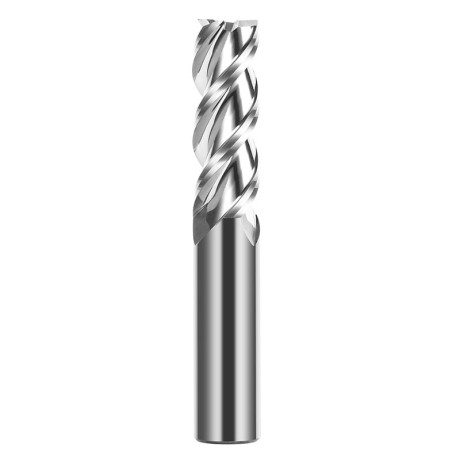
 3-Flute End Mills 0.00
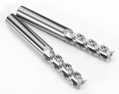
3-Flute Carbide End Mill VHM Z-3 for Aluminium| TriMill AL
Ø1x3xD4x50L Ø1.5x5x4Dx50L Ø2x6x4Dx50L Ø2.5x8x4Dx50L Ø3x9x3Dx50L + 41 morePrice €5.10Price €4.15without VAT -
Bestseller
 Countersinks 0.00
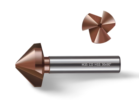
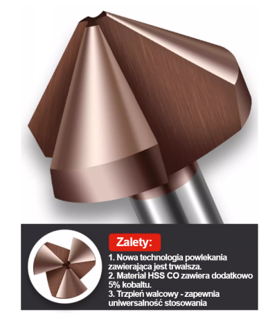
3-Flute Countersink Fi4.5-fi60, 90° - HSS-CO - 5% Kobaltu | Straight Shank
Ø4.5 x 4 x 90° x 40L Ø5 x 5 x 90° x 45L Ø6.3 x 5 x 90° x 45L Ø8.3 x 6 x 90° x 50L Ø10.4 x 6 x 90° x 50L + 12 morePrice €4.81Price €3.91without VAT -
Bestseller
 3-Flute End Mills 0.00
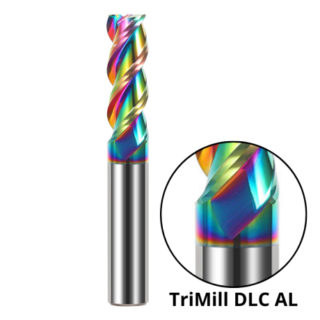
3-Flute DLC Coated Carbide End Mill | TriMill DLC AL
Ø1x3x4Dx50L Ø1.5x5x4Dx50L Ø2x6x4Dx50L Ø2.5x8x4Dx50L Ø3x8x3Dx50L + 38 morePrice €5.07Price €4.12without VAT